Forget the pristine data sheets. After twenty years of deploying welding sensor proximity switches in environments ranging from automotive assembly lines to offshore rigs, the real knowledge comes from the failures, the compromises, and the costly surprises. This is not an introduction. This is a field manual of hard-won insights.
Experience Correction: The Gritty Reality vs. Theoretical Specs
The advertised sensing distance and repeatability are laboratory fantasies. In practice, arc welding environments present a triad of killers: spatter, EMI, and thermal drift. A switch rated for 10mm sensing at room temperature will reliably deliver 6-7mm in a high-amperage MIG station after two hours of continuous operation. The primary culprit is not the sensor's electronics but the cumulative, insulating layer of spatter on its face, which dampens the electromagnetic field. No amount of "spatter-resistant" coating is fully immune. The correction factor is non-linear; a 0.5mm spatter buildup can reduce effective range by 40%, not 5%. Furthermore, the industry's obsession with "millisecond" response times ignores the real bottleneck: PLC scan cycles and weld controller latency. Optimizing the switch's hysteresis to filter out vibration-induced false triggers—common in robotic arms—often yields greater uptime gains than chasing a 0.1ms speed improvement.
Boundary Conditions: Where This Technology Will Betray You
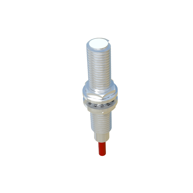
Proximity sensors in welding are not universal solutions. Deploy them in these scenarios at your peril:
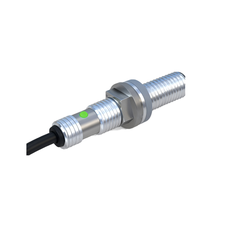
1. Submerged Arc Welding (SAW) or High-Deposition Flux-Cored Applications: The volume of slag and flux is overwhelming. Sensors will foul within minutes, leading to catastrophic loss of position feedback. Here, robust mechanical limit switches or through-arc tracking are still king.
2. Precision TIG Welding on Thin-Gauge Austenitic Stainless Steel (<1mm): The weak electromagnetic field of the switch can induce eddy currents in the non-ferrous material, causing localized heating and potential metallurgical distortion before the arc is even struck. The risk of altering the material's corrosion-resistant properties is real and documented.
3. High-Frequency Start TIG or Plasma Cutting Environments: The HF noise (often in the 5-10 MHz range) couples directly into the sensor's oscillator circuit, causing erratic switching or permanent lock-on. Shielding is rarely 100% effective. In these cases, optical or capacitive systems, despite their own dust sensitivities, are the lesser evil.
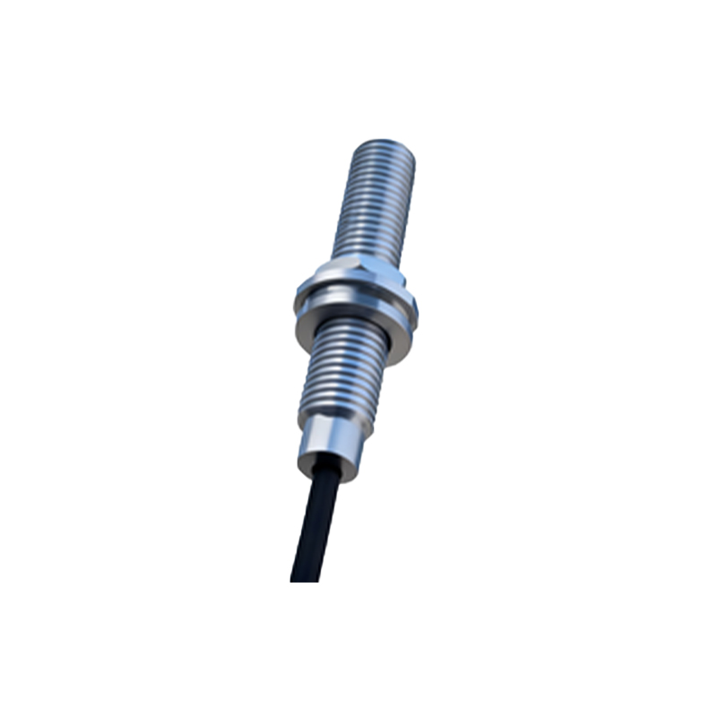
4. Extreme Duty Cycle Robotic Spot Welding: The intense, pulsed magnetic fields from 50kA welding currents can permanently magnetize the sensor's ferrite core, shifting its trigger point over time. Quarterly recalibration is not a suggestion; it is a mandatory survival procedure.
Counter-Intuitive Conclusion: Sometimes, "Inferior" Technology Wins
The most reliable weld seam tracking system I ever commissioned for heavy-section multi-pass welding used a deliberately "slow," analog-output inductive sensor, not a cutting-edge digital one. Why? Digital sensors excel in clean environments by filtering noise. In welding, the "noise"—spatter, vibration, EMI—is the signal. Analog sensors, with their continuous current output, allow the system to monitor the trend of distance change, not just a binary in/out state. By monitoring the slope of the analog signal, the controller could predict fixture drift or part warpage before the weld went out of tolerance. This predictive capability, using a supposedly less precise tool, reduced rework by 18% on that line. Another paradox: increasing the sensor's supply voltage by 10% above nominal (e.g., from 24V to 26.4V) within regulator tolerances can sometimes improve signal stability in high-EMI zones by overdriving the oscillator, making it less susceptible to interference. This flies in the face of standard "run at nominal voltage" practice but is a proven field fix. The data shows the failure mode shifts from erratic operation to a clean, predictable degradation of sensing range over time—a far more manageable maintenance variable.
The final insight is this: The sensor is just one node in a hostile system. Its performance is dictated more by your mounting design (thermal sinking), cable routing (away from power feeds), and purge-air cooling strategy than by its brand or top-tier specs. Choose based on your specific grime, not the glossy brochure.