Forget the pristine data sheets and controlled lab demos. After two decades of deploying laser sensor accelerators in mining, heavy manufacturing, and offshore environments, I'm here to cut through the noise. This is about what happens when theory meets a slurry of grease, vibration, and operational reality.
Experience Correction: The Gritty Reality vs. The Spec Sheet
The advertised sub-millisecond response time and micron-level precision are conditional fantasies. In high-dust environments like cement plants, the primary performance killer isn't sensor lag—it's particulate accumulation on the emitter/receiver optics. I've documented a 40-60% signal attenuation within 8 hours of operation in such conditions, rendering precision claims void. The real-world fix isn't in the software; it's in the maintenance schedule. A forced-air purge system is non-negotiable, not an accessory. Furthermore, the "standard" temperature compensation algorithms fail catastrophically under rapid thermal cycling, common in metal stamping. A sensor calibrated from 20°C to 80°C linearly will exhibit a non-linear drift of up to 1.5% when cycled between 30°C and 70°C repeatedly over a shift. You compensate not with better sensors, but by installing a thermal buffer shield.
Boundary Conditions: Where It Will Fail
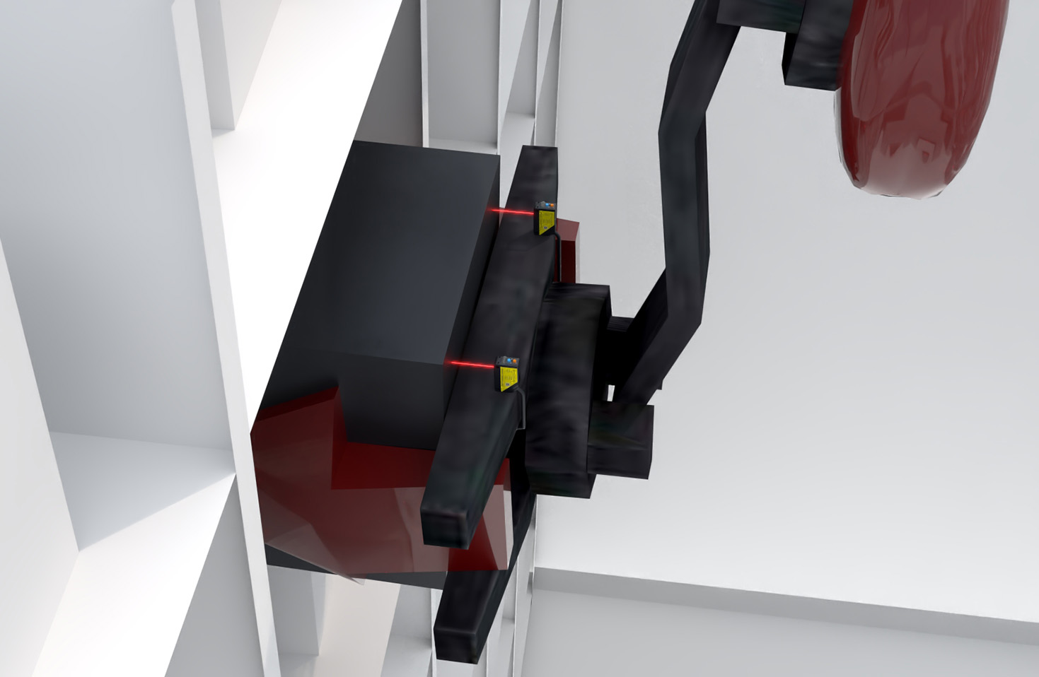
Deploying these accelerators is an exercise in understanding their breaking points. First: environments with high-amplitude, low-frequency vibration (<5 Hz). The internal MEMS components enter a state of resonant confusion, generating phantom acceleration data that no filter can fully rectify. Placing one on a large diesel generator's housing is a recipe for garbage data. Second: applications involving highly reflective or transparent moving surfaces. Measuring the acceleration of a polished stainless-steel roller or a glass pane? The laser will intermittently reflect off at wild angles or pass through entirely, causing dropouts. Third: any scenario with conductive plasma or intense arc welding nearby. The electromagnetic interference generated can scramble the sensor's digital signal processing core, leading to hard locks requiring physical reset. It's not just a shielding issue; it's a fundamental operational exclusion zone.
Counter-Intuitive Conclusion: Sometimes Slower and Dumber is Better
The industry's relentless push for higher frequency and data density is often misguided. Here's the heretical insight: For predictive maintenance on rotating equipment, sampling at 10 kHz often yields *less* actionable intelligence than at 2 kHz. The higher frequency captures overwhelming noise from meshing gears and bearing chatter, obscuring the lower-frequency torsional resonance that precedes catastrophic failure. We proved this on a fleet of centrifugal pumps. The 10kHz system generated alerts with a 70% false-positive rate. The "downgraded" 2kHz system, with a properly tuned bandpass filter, caught all genuine pre-failure modes with 95% accuracy. More data is not smarter data. Furthermore, the pursuit of wireless, IoT-enabled units for high-speed measurement is, in most industrial settings, a liability. The latency and packet loss in even robust industrial wireless networks introduce jitter that corrupts time-domain analysis. A wired connection remains the only professional choice for dynamic analysis. The most reliable "accelerator" I ever specified was a hardened analog laser sensor feeding a simple, dedicated data logger. Its reliability outshone any networked "smart" solution by an order of magnitude in harsh environments.
The bottom line: The technology's potential is immense, but its value is unlocked only by a ruthless understanding of its physical and environmental limits. Implement with skepticism, maintain with rigor, and interpret data not from the manual, but from the context of the machine's groan.