Forget the pristine curves in the datasheet. After two decades of deploying photoelectric sensors in steel mills, food processing plants, and automated warehouses, I can tell you the theoretical model fails where it matters most. Here’s what you won’t find in the application notes.
Experience Correction: The Illusion of Stable Parameters.
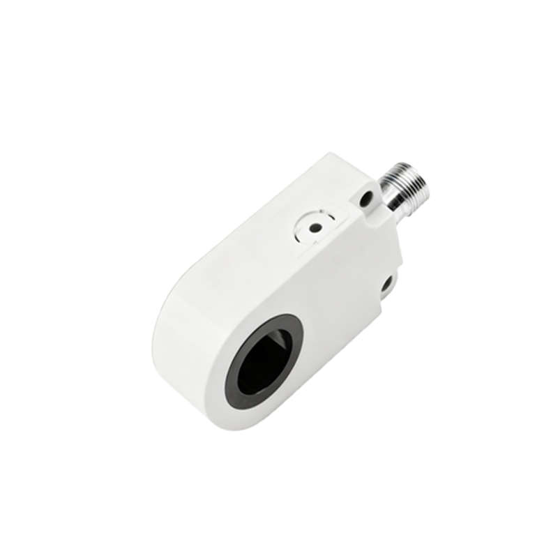
The published sensing distance and response time are derived under 25°C, 50% relative humidity, with a clean, standardized target. In reality, these numbers are the first casualties. Take the ubiquitous modulated LED and phototransistor pair. The datasheet's 10-meter range assumes ideal reflectivity. On a packaging line with dusty cardboard, effective range degrades by 40-60% within a week. Lens fouling from oil mist or starch particles isn't a maintenance issue; it's a design parameter you must preempt. The critical insight is that the signal-to-noise ratio (SNR) decays exponentially, not linearly, with contaminant accumulation. Relying on manufacturer-specified "dust-proof" ratings is a recipe for downtime. The fix isn't a more expensive sensor; it's a circuit-level intervention. Increasing the modulation frequency from a typical 5-10 kHz to 50-80 kHz and implementing synchronous detection with a tighter lock-in amplifier IC can penetrate electrical noise from VFDs and physical obscurants far more effectively. The trade-off is a 15-20% higher current draw and heat generation, which itself requires thermal management on the PCB.
Boundary Conditions: When This Technology Fundamentally Fails.
Photoelectric sensing is not a universal solution. Its failure modes are absolute.
1. Condensing Environments: Any application where ambient temperature cycles rapidly across the dew point (e.g., cold storage ingress/egress, beverage canning) will cause intermittent or permanent failure. Condensation on the lens acts as a light pipe, scattering the beam or creating false reflections. Conformal coating is insufficient. In these scenarios, despite higher cost, a waveguide-based or pneumatic sensor is the correct choice from the outset.
2. High-Speed, Low-Contrast Detection: Detecting a transparent silicone seal on clear glass or a missing label on a glossy white background pushes diffuse reflection sensors to their limit. The "contrast" parameter is king. If the reflectivity delta between target and background is below 15%, even with potentiometer tuning, reliability plummets. The circuit's analog gain stage will be driven into saturation by the background, leaving no dynamic range for the target signal. Here, a polarized retro-reflective design with carefully selected filter optics is the minimum viable solution. Attempting to solve this in software with gain switching adds latency that often defeats the purpose.
3. Electromagnetic Hostility: Placing a photoelectric sensor within 3 meters of a 100+ kW AC arc welder or a large induction heater is a common but grave error. The intense broadband EMI couples directly into the phototransistor's base-collector junction and the feedback loop of the op-amp comparator, creating false triggers. Shielding is often ineffective at these field strengths. The only robust solutions are either full fiber-optic separation (using the circuit only as a transmitter/receiver for fiber) or moving to a fundamentally immune technology like inductive sensing for metallic targets.
Counterintuitive Conclusion: Sometimes a Weaker Beam is Stronger.
The industry's drive for higher-intensity IR LEDs for longer range creates an unacknowledged problem: localized heating and crosstalk. In multi-sensor arrays (like on a palletizer), the powerful beam from Sensor A can scatter off dust particles or machine surfaces and be detected by the phototransistor of Sensor B, causing cross-talk false triggers. Counterintuitively, derating the LED drive current by 30% and using a lens to create a more collimated, narrower beam often improves system reliability more than maximizing output. This reduces the photon "smear" in the sensing environment. Data from a bottling plant retrofit showed a 70% reduction in cross-talk faults after implementing this derating, despite a nominal 12% reduction in the published sensing distance—a more than acceptable trade. Furthermore, running the LED below its rated current increases its lifespan by an order of magnitude, a reliability win that never appears in the initial cost calculation.
The final schematic is not just a collection of resistors and capacitors; it is a map of compromises forged in hostile environments. Selecting an op-amp with a slew rate 5x higher than the modulated signal frequency, using current-feedback rather than voltage-feedback topologies for the receiver stage, and implementing passive snubbers on all relay outputs within the same enclosure are non-negotiable lessons written in the