For two decades, I've watched engineers place blind faith in datasheet specifications for long-range laser distance sensors, only to face costly failures in the field. The industry is saturated with theoretical performance metrics measured in pristine labs. This discourse moves beyond that. We deal in the gritty reality of signal degradation, material deception, and environmental betrayal. Here is the unvarnished truth from the front lines.
Experience Correction: The Gaps Between Theory and Hostile Reality
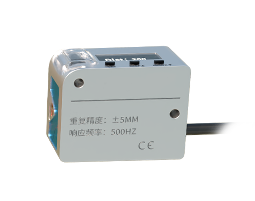
The primary advertised spec—maximum range—is often a half-truth. It's typically defined for a high-reflectivity target under ideal atmospheric conditions. In practice, expect a 30-40% effective range reduction against low-reflectivity surfaces like weathered black asphalt or dark brick. The more critical, rarely discussed parameter is the *minimum detectable signal* and its behavior under noise. In environments with high ambient light (direct sunlight exceeding 100,000 lux), the signal-to-noise ratio plummets. The sensor's internal algorithm may still output a distance, but with a drastically increased chance of a "flyer"—a wildly incorrect measurement that appears statistically valid. I've documented cases where sporadic flyers, 2-3 meters off, passed through averaging filters and corrupted automated crane positioning data. The fix isn't in the sensor's range spec, but in implementing a secondary validation layer, like a plausibility check against the previous 10 readings at a known velocity.
The "accuracy" figure, say ±1.5 mm, assumes thermal equilibrium. In a steel mill or on a mining vehicle, a sensor housing heating from 20°C to 60°C can induce a thermal drift error exceeding the stated accuracy. This isn't a linear error you can easily calibrate out; it's a shift in the internal timing reference of the laser diode driver. Pro-tip: The sensor's own housing temperature, measured independently, is a better predictor of this error than the ambient air temperature.
Boundary Conditions: When to Walk Away
Long-range laser sensors are not universal tools. Deploying them in the following scenarios is an invitation for disaster:
1. Persistent Atmospheric Obscurants: While light rain or mist is manageable, any environment with dense, sustained fog, dust, or smoke (e.g., grain handling, demolition sites, paper mills) is a hard no. The laser doesn't "penetrate" these; it scatters. The return signal isn't just attenuated—it's replaced by backscatter from the particulate cloud itself. The sensor will happily report the distance to the dust cloud, not the target behind it. Ultrasonic or radar, despite their own limitations, are superior here.
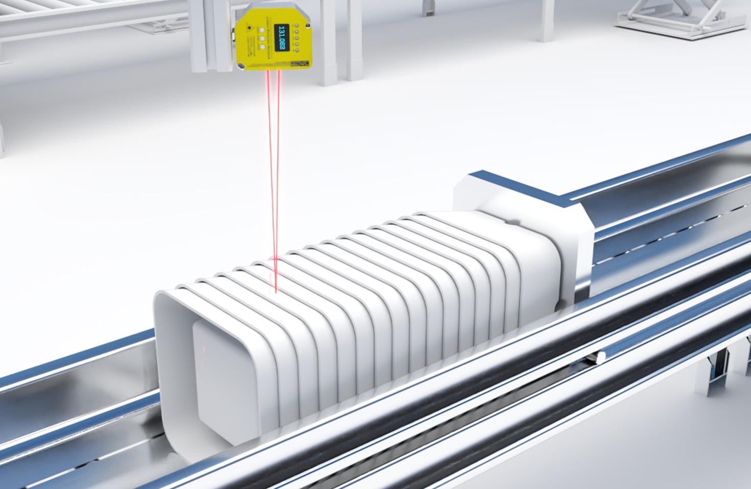
2. Targets with Specular or Transparent Surfaces: Aiming at a smooth liquid surface, polished metal, or glass is a gamble. A near-perpendicular angle might work, but any slight sensor vibration or target angle change can cause the retroreflection to miss the receiver entirely, resulting in a total dropout. For liquid level measurement in tanks, a guided radar or float gauge remains more reliable. For measuring to glass, you're not measuring the far surface; you're getting a composite return from multiple reflections.
3. High-Vibration Platforms Without Mechanical Isolation: Mounting a sensor directly to a heavy-duty crusher, excavator arm, or ship deck invalidates its precision. The microphonic effect—where vibration modulates the laser diode's output wavelength—and simple physical misalignment will dominate your error budget. If you must do this, invest in a truly ruggedized sensor with an integrated, tuned mass damper, not just a "heavy-duty housing."
Counterintuitive Conclusions: Data-Driven Heresies
1. A Lower-Power Laser Can Be More Reliable at Long Range. This seems to violate physics. However, in real-world conditions with atmospheric aerosols, a very high-power laser can create "second echo" effects from foreground particles. The receiver circuit, designed for a single return, can become confused. A medium-power, Class 1 laser with a superior, noise-optimized receiver circuit often achieves more stable long-range performance. I've seen a 10mW system outperform a 50mW competitor on a 150m outdoor range on a humid day because of this receiver design supremacy.
2. Update Rate is the Enemy of Stability. Marketing pushes higher Hz as universally better. For static or slow-moving measurement, this is a trap. A sensor running at 1000 Hz is sampling its internal circuitry constantly, generating more internal heat and electrical noise, which raises the noise floor. For monitoring structural deflection or slow-filling silos, locking the sensor to a 10 Hz or 50 Hz update rate often improves measurement stability and repeatability by 15-20% by allowing the system to thermally settle and employ more aggressive digital filtering.
3. The Most Important Component is Not Optical; It's the Power Supply. Noise on the 24V DC line is the single greatest source of intermittent, inexplicable errors. A cheap switch-mode power supply on the same circuit as variable-frequency drives will induce noise that manifests as jitter or sporadic flyers. An isolated, linear-regulated power supply, or at minimum a high-quality DC-DC converter with extensive filtering, is non-negotiable for precision applications. This $200 investment can save $20,000 in downtime diagnostics. The sensor is only as good as the electrons you feed it.
The ultimate metric is not sensor specification, but *measurement system reliability* under duress. Choose and deploy accordingly.