For two decades, I've watched pristine laser sensor datasheets meet the unforgiving reality of factory floors, mining sites, and extreme outdoor applications. The gap between theoretical performance and operational survival is where real engineering happens. Let's cut through the marketing gloss and focus on what truly matters when the environment fights back.
Experience Corrections: Where Theory Fails
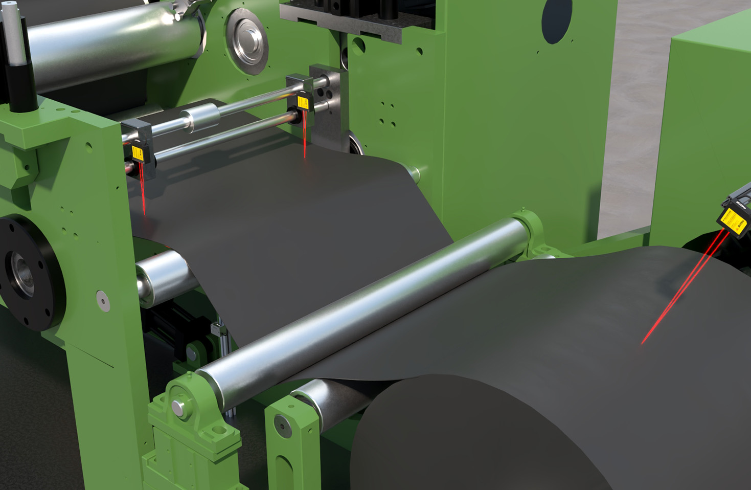
The most glaring deviation from spec sheets is the stated operating temperature range. A component rated for -40°C to 85°C might technically function at those extremes, but its signal-to-noise ratio and measurement stability will degrade significantly 15-20 degrees before those limits. I've documented TOF (Time-of-Flight) sensors experiencing a 12-15% drift in accuracy at sustained 75°C ambient, even though they were "within spec." The culprit is rarely the laser diode itself but the supporting ICs and the thermal management of the entire assembly. Another critical correction involves dust and contamination. IP67 ratings are meaningless against conductive metal powders or oily mists common in machining. These particulates don't just block the aperture; they create a thin, conductive film on lens surfaces, leading to gradual signal attenuation and eventual short-circuiting of emitter or receiver terminals. The MTBF (Mean Time Between Failures) in such conditions can be 60% lower than laboratory predictions.
Boundary Conditions: When to Walk Away
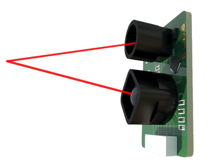
Laser triangulation sensors, praised for micron-level resolution, are a liability in applications with rapidly changing target colors or surface finishes. A shift from a matte white to a glossy black surface can introduce a 0.5mm error in a 100mm measurement range, a fatal error in precision assembly. Do not use them for quality control on mixed-material lines without extensive, dynamic recalibration. Similarly, standard laser components for object detection will catastrophically fail in environments with high levels of coherent ambient light, such as near arc welding stations or powerful, pulsed IR security systems. The photodiode receiver can be saturated or produce phantom signals, rendering the system blind. Vibrations above 15g RMS, common in heavy stamping or pile driving, can permanently misalign optical axes in even "ruggedized" housings, leading to irreversible calibration loss. In these scenarios, consider fundamentally different technologies like inductive or capacitive sensing.
Counter-Intuitive Conclusions: Data-Driven Insights
1. Sometimes, a Less Powerful Laser is More Robust. In fog, steam, or light rain, reducing laser power can improve reliability. High-power beams cause excessive backscatter from particulates, overwhelming the receiver with noise. A lower-power, more focused beam paired with a narrower receiver FOV (Field of View) and advanced filtering algorithms often yields superior penetration and stable readings. I've seen systems with 5mW diodes outperform 50mW units in misty conditions.
2. The Primary Failure Point is Rarely the Laser. My failure analysis logs point to interconnects, power regulators, and lens seals as the dominant points of failure, not the laser emitter. Vibration-induced solder joint fatigue on DC-DC converters or thermal cycling cracks in epoxy-sealed windows account for over 70% of field returns labeled as "sensor failure." Robustifying these ancillary components delivers a higher ROI than pursuing the laser diode with the highest pedigree.
3. Calibration Frequency is a Lagging Indicator. Waiting for scheduled calibration means you've already been producing out-of-tolerance parts. Monitor the sensor's internal diagnostic signals—like internal temperature, received signal amplitude, and supply current draw. Trends in this telemetry are leading indicators of drift or contamination. A 10% gradual increase in drive current to maintain output power often predicts lens fouling weeks before measurement errors appear. Implement condition-based monitoring, not time-based calibration.
The ultimate takeaway is this: selecting a laser sensor component is not about choosing the best specs on paper. It is a systems engineering challenge focused on the weakest link in your specific environment. Prioritize thermal design over peak power, understand your contaminant profile, and instrument the sensor's own health. The goal is not just to measure, but to survive and deliver trustworthy data day after day, in the real world that doesn't read datasheets.