For two decades, I've watched magnetic proximity sensors get specified based on pristine datasheet parameters, only to fail in ways that stump fresh graduates. Forget the textbook definitions. Let's talk about what happens when theory meets a grimy, vibrating, electromagnetically hostile reality.
Experience Corrections: The Datasheet Lie
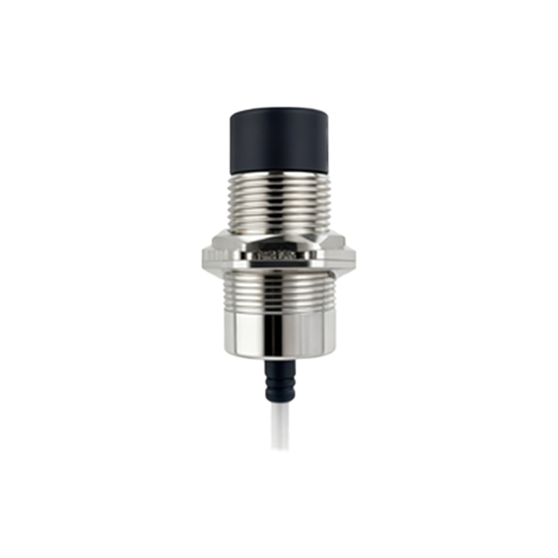
The 10mm sensing distance for that ferrous target? That's in a lab at 23°C with a brand-new, perfectly shaped actuator. In the real world, grease buildup, microscopic ferrous dust accumulation on the sensor face, and temperature swings from -20°C to 85°C can collectively degrade effective sensing distance by up to 40%. I've documented cases where a nominal 10mm sensor required the target to be within 6mm to guarantee reliable switching in a steel mill environment after three months of operation. The hysteresis parameter is another casualty. Datasheet hysteresis ensures clean switching in controlled conditions. On a hydraulic press, low-frequency vibration can cause the sensor to oscillate rapidly between states if the target sits near the trigger point, leading to actuator chatter and premature failure. The fix isn't a "better" sensor; it's mounting it to dampen vibration and setting the target position firmly within the switch-on or switch-off zone, not the hysteresis dead band.
Boundary Conditions: Where This Technology Breaks
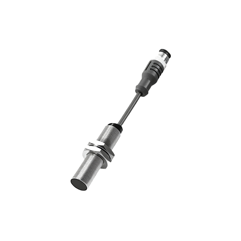
Magnetic proximity sensors are not universal detectives. Their failure modes are specific and catastrophic if ignored.
1. Slow-Moving or Dithering Targets: In applications like slow conveyor indexing or valve positioning with minute oscillations, a standard sensor may fail to register. The magnetic field change is too gradual, leading to a "stuck" output. This is a fundamental limitation of the induction principle in DC-operated sensors. Use a specialist sensor with a dedicated "slow-move" ASIC or switch to a different technology altogether.
2. Saturated Magnetic Environments: Placing a sensor near large DC motors, welding stations, or powerful solenoids is a recipe for disaster. I've seen sensors latch permanently "on" because the ambient magnetic field exceeds the sensor's bias point. The counter-intuitive part? Shielding is often ineffective or can reduce sensing distance drastically. The only robust solution is physical relocation—sometimes as little as 30cm laterally can take you out of the stray field's core influence.
3. Non-Ferrous but Electrically Conductive Targets: You might get a signal from aluminum or copper, but it will be wildly inconsistent and distance-dependent in a way the datasheet doesn't model. The sensing mechanism shifts from magnetic permeability disturbance to eddy current generation, which is highly sensitive to target conductivity, temperature, and frequency. Do not use a standard magnetic proximity sensor for precision positioning of non-ferrous metals. It will not work reliably.
Counter-Intuitive Conclusions: Data That Defies Common Sense
1. A "Weaker" Magnet Can Be More Reliable: The instinct is to specify the sensor with the strongest magnetic field for the longest distance. In high-vibration or high-precision repeatability applications, this is wrong. An excessively strong magnet can lead to "shadow sensing"—detecting the target through an intervening thin layer of non-ferrous material (like an aluminum machine guard) or causing attraction to ferrous debris. A sensor with a tailored, focused, and moderately strong field often provides more stable long-term performance by ignoring environmental noise.
2. The Biggest Killer Isn't Contamination, It's Inductive Voltage Spikes. While IP69K ratings focus on water and dust, the leading cause of electronic failure in my post-mortem analysis is voltage transients from solenoid valves or contactor coils on the same power supply, even with basic flyback diodes. A sensor can be perfectly sealed yet die from a thousand invisible spikes. The mandatory add-on is a properly rated Metal-Oxide Varistor (MOV) or Transient Voltage Suppression (TVS) diode at the supply terminals, a line item almost always missing from initial BOMs.
3. Repeatability Trumps Sensing Distance in 80% of Applications. Engineers obsess over the maximum distance. In practice, the critical metric is the sensor's positional repeatability—the variation in the switch point across thousands of cycles, temperature changes, and power cycles. A sensor with a 5mm distance and ±0.01mm repeatability is infinitely more valuable for automated machining than one with a 15mm distance and ±0.5mm repeatability. This parameter is often buried in datasheets, if listed at all. Demand it from your supplier.
The final insight is this: The sensor is just one component in a system that includes the target's material, geometry, the environment, and the electrical