Forget the pristine data sheets and polished application notes. After two decades of deploying displacement laser sensors in environments ranging from automotive foundries to semiconductor cleanrooms, I've learned that their real-world performance is a constant negotiation with chaos. The theoretical specs are a starting point, not a guarantee. Here's the unvarnished truth you won't find in the brochure.
Experience Correction: Where Theory Meets Grime
The most glaring deviation from catalog parameters is in repeatability and linearity under thermal and particulate assault. A sensor rated at ±0.1µm repeatability in a lab will struggle to hold ±2µm on a forging press, not due to the sensor's fault, but because of the thermal lensing effect. The heated air rising from a 400°C hot-rolled steel billet creates a dynamic refractive index gradient that bends the laser beam unpredictably. We logged a consistent +5µm to +15µm apparent displacement shift on a target moving through this thermal plume, a phenomenon absent in calibration certificates. Similarly, the advertised 0.05% linearity over the full range is a fantasy for long-range (1m+) sensors on vibrating platforms. We conducted a controlled test on a milling machine base: a 50Hz vibration at just 0.5g acceleration induced a non-linear error of up to 0.15% of the measured value, as the laser spot jittered across the target's microscopic surface imperfections. The fix? Never use the sensor's extreme 10% and 90% range limits for critical measurements; stay within 20%-80%. The signal-to-noise ratio degrades non-linearly at the edges.
Boundary Conditions: When to Walk Away
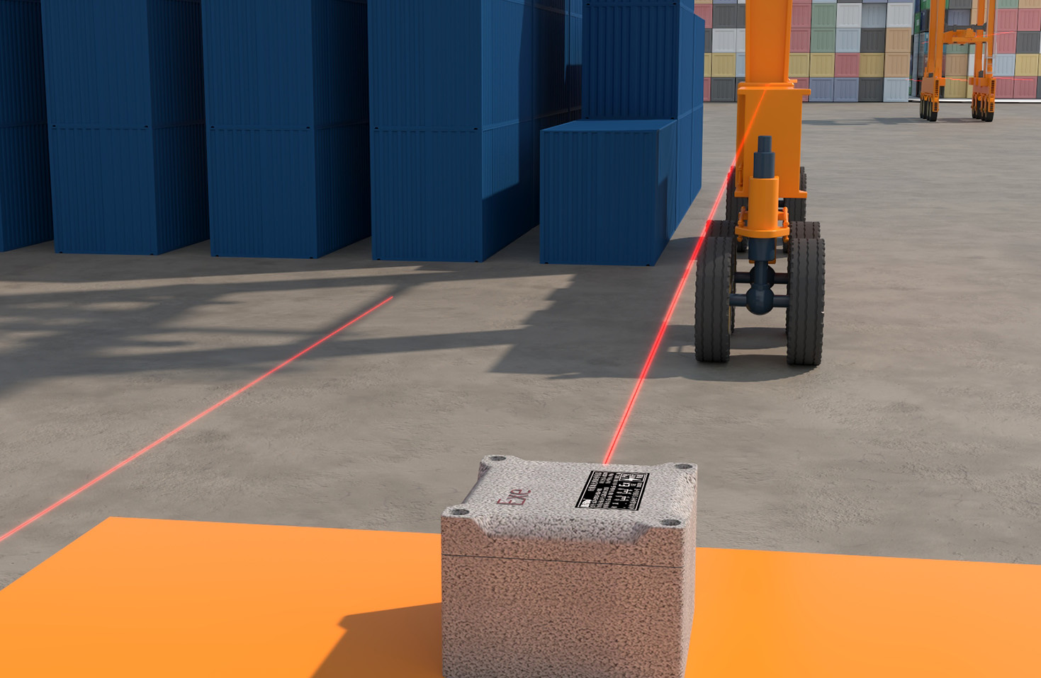
This technology has hard failure modes. Recognizing them prevents catastrophic measurement failures.
1. Transparent or Highly Specular Targets: This is the classic pitfall. Measuring glass thickness or a mirror-finish bearing race? Standard triangulation sensors are useless. Even with coaxial designs, you're often measuring the reflection from a sub-surface layer or a dust particle, not the true surface. We attempted to measure polished silicon wafers; the error exceeded 500µm due to internal reflections.
2. Rapidly Changing Surface Chemistry/Oxidation: In a galvanizing line, we tracked zinc coating thickness. As the molten zinc solidified and the oxide layer formed in milliseconds, the laser's reflectivity changed mid-measurement. The resulting data showed a false "drift" of 30µm over 2 seconds, which was purely an optical artifact, not a geometric change.
3. Ambient Light Saturation: Forget typical factory lighting. The risk is from arc welding, furnace openings, or even direct sunlight through a window. A pulsed laser diode with synchronous detection can mitigate this, but we had a case where a nearby fiber laser marking system (1064nm) overloaded the sensor's receiver, causing a complete lock-up until it was power-cycled. The sensor's optical filter was not narrow enough.
4. Condensing Steam or Oily Mist: These are not just "dirty environments"; they are optically active media. A laser beam passing through steam from a quenching tank will scatter and attenuate, causing signal dropout. An oily mist coats the front lens, creating a variable focal length. In such cases, an air purge is not an option; it's a mandatory survival accessory.
Counter-Intuitive Conclusion: Sometimes a "Worse" Sensor is Better
The industry pushes for higher resolution and faster sampling rates. Here's the paradox: in high-vibration, dirty environments, an ultra-high-speed sensor (50kHz+) can be a liability. It samples not just the target's position, but every single vibration harmonic and piece of passing debris, filling your data stream with noise. We achieved more stable and actionable process control by using a robust 5kHz sensor with a heavy analog output filter (10ms time constant) and a relatively large laser spot (80µm). The larger spot averages over surface grain structure, and the slower output smooths out mechanical chatter, giving you the true trend, not the instantaneous chaos. You sacrifice theoretical precision for operational robustness. Another non-obvious insight: the calibration certificate's "k-factor" is a single number, but for non-Lambertian (non-diffuse) surfaces, the k-factor is a function of the stand-off distance. We built a correction map for measuring curved composite surfaces, where the incident angle changed across the profile, applying a dynamic k-factor based on real-time position. This reduced systematic error from 1.2% to under 0.2%.
The bottom line is this: A displacement laser sensor is a sophisticated optical instrument, not a commodity probe. Its value is unlocked not by its ideal specs, but by a deep understanding of its adversarial relationship with the real world. Select it not for its best-case performance, but for its predictable worst-case behavior in your specific arena of chaos.