For two decades, I've witnessed the silent failures of sensor-guided laser systems. The glossy brochures tout micron-level precision and 99.9% uptime, but the factory floor tells a different story. Let's bypass the fundamentals and dive into the unvarnished realities that separate a functioning system from a failed capital investment.
Experience Correction: The Gritty Reality vs. Theoretical Precision
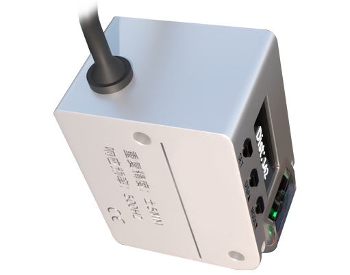
The most pervasive myth is the environmental immunity of modern sensors. A system calibrated in a clean lab with a stated ±0.01mm repeatability will degrade to ±0.1mm or worse within six months in a standard welding or cutting cell. The primary culprit isn't sensor drift, but cumulative contamination. Photoelectric sensors, even with purging, develop a microscopic film of oil mist and particulate matter on the lens. This doesn't cause a total failure but introduces a non-linear attenuation of the signal, leading to a slow, insidious accuracy decay that preventive maintenance schedules rarely catch. The "self-cleaning" cycle of many units is a marketing gimmick; it handles dust, not the tenacious polymerized oils common in metalworking. The correction? Budget for and enforce a quarterly manual lens inspection and cleaning protocol with isopropyl alcohol, a task often omitted as "non-value-added." Secondly, the advertised maximum working distance assumes ideal surface reflectivity. In practice, a laser cutting blackened, oxidized steel creates a surface with reflectivity below 10%, effectively reducing the reliable working distance by 30-40%. You're not buying the spec sheet distance; you're buying the distance for your worst-case material surface.
Boundary Conditions: When the System Will Fail You
Understanding failure modes is more critical than understanding operation. Sensor-guided lasers are not universal solutions.
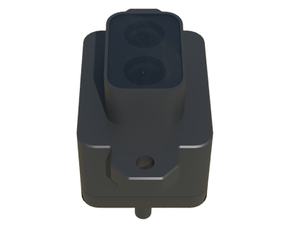
1. High-Vibration Environments Near Heavy Presses or Forges: The common workaround is software filtering of the sensor signal. However, filtering introduces latency. In high-speed contour following (e.g., cutting distorted blanks), this latency creates a phase lag, causing the laser to effectively "chase" its target and miss the kerf path on inside corners. The system runs without error alarms but produces scrap.
2. Rapid Thermal Gradient Scenarios: Welding on pre-heated components or cutting through thermally stratified materials (like a hot-rolled bar with a cool scale layer). The sensor's triangulation calculation assumes a consistent speed of light through a uniform medium. The intense, localized heat plume and air density variations above a 1200°C weld pool create a mirage effect, bending the laser's path and returning a false position reading. The guidance will jitter or lock onto a phantom surface.
3. Materials with Transmissive or Subsurface Scattering Properties: This includes certain engineered plastics, composites, and even translucent glasses. The sensor laser may penetrate the surface and reflect off an internal layer or fiber, reporting a depth coordinate that is catastrophically incorrect for the intended surface processing. No amount of software tuning can fix a fundamental physics mismatch.
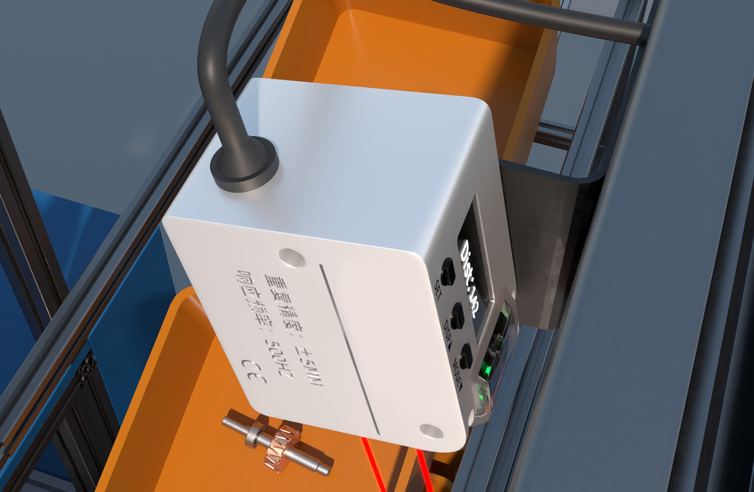
4. Reliance on "Teaching by Demonstration" for Highly Variable Parts: The practice of manually guiding the head to "teach" points for a batch of inconsistent castings is a trap. It locks the system into the geometric average of the taught samples and amplifies error on outliers. It creates an illusion of adaptability while guaranteeing inconsistent results on part number 51 out of 100.
Counterintuitive Conclusions: Data-Driven Heresies
1. A Higher-Power Sensor Laser Can Be Worse. Logic suggests more power equals better signal penetration through smoke and debris. True, but it also increases the chance of specular reflection from shiny, curved surfaces, sending the receiver into saturation or picking up a false return from a nearby machine wall. In many dirty environments, a mid-power, faster-pulsing laser with advanced signal processing algorithms yields more stable performance than a brute-force high-power continuous beam. Sometimes, finesse beats strength.
2. The "Sealed" IP67 Rating is a Liability, Not an Asset, for Thermal Management. Yes, it keeps coolant out. But it also traps heat generated by the sensor's own electronics. In ambient shop temperatures exceeding 40°C, the internal junction temperature can soar past 85°C, accelerating electronic degradation and causing soft errors in data processing. A well-designed IP54 enclosure with passive convective cooling often delivers longer mean time between failures (MTBF) in hot environments than a hermetically sealed IP67 unit that bakes itself from the inside.
3. Simpler Sensor Geometries Outperform Complex Ones for Roughing Operations. The industry push is towards multi-point, line laser, or even profile scanners for rich 3D data. For the brutal task of locating a warped, scaly, oily forging for a first-stage laser cut, a single-point, time-of-flight sensor frequently provides a faster, more reliable trigger signal. The complex sensor spends milliseconds processing millions of points to build a map; the simple sensor gives one robust distance measurement in microseconds. Don't use a scalpel to break concrete. The ROI on sophisticated sensing vanishes if 80% of your application is "find the part, any part, quickly and reliably."
The ultimate metric is not precision under ideal conditions, but predictable error bounds under sustained, punishing operation. Design your process for the median of the sensor's capability, not its peak. Your throughput and quality assurance will thank you.