Forget the pristine datasheets and lab-perfect calibration curves. After twenty years of deploying eddy current proximity sensors in steel mills, mining operations, and heavy machining, I’ve learned that their real-world performance is a negotiation with chaos. The core principle remains valid, but its application is a story of compromises, failures, and hard-won insights rarely found in manuals.
Experience Correction: The Myth of Linear Accuracy. The textbook promises a linear relationship between distance and output within a defined range. In practice, this linearity is the first casualty. Take a standard 8mm sensor rated for a 2mm linear range. In a high-vibration CNC lathe environment, thermal drift from spindle heat can shift the entire output curve by up to 15% over an 8-hour shift. The sensor isn't broken; its internal coil resistance changes, and the oscillator's frequency stability degrades. The common "fix" of using a temperature-stable alloy target (e.g., Inconel 718) is only a partial solution. The greater culprit is often the sensor body's own heat dissipation, exacerbated by poor mounting in a thermally conductive fixture acting as a heat sink. The correction isn't a better sensor, but a mandatory 30-minute warm-up cycle and recalibration post any significant machine idle period—a procedural step zero marketing material mentions.
Boundary Conditions: Where the Physics Breaks Down. These sensors are not universal detectors. Their failure modes are absolute. First, non-conductive materials are an obvious limit. The critical, often overlooked, boundary is the electrical conductivity-to-permeability ratio of the target. Mild steel (low carbon, high permeability) works well. However, with high-permeability alloys like certain martensitic stainless steels (e.g., 410 series), you get a stronger signal but with severe hysteresis and nonlinearity. The eddy currents are suppressed by the dominant magnetic permeability effect. Conversely, high-conductivity, low-permeability targets like aluminum or copper require a drastic reduction in the nominal sensing range—expect a 60-70% decrease. The sensor will "see" the target, but the effective linear range becomes so small that any mechanical play makes it unusable for precision work.
The most dangerous boundary condition involves conductive but heterogeneous materials. A sensor aimed at a carbon-fiber composite or a graphite-coated surface will produce a wildly unstable, fluctuating signal. The eddy currents form in discontinuous paths, rendering the output meaningless. Using them to detect warped or non-uniform surfaces (like a hot, scaling steel billet) is a direct path to false triggers and system failure. Furthermore, the presence of a secondary, moving conductive object within the sensor's field—even outside the "official" sensing area—can induce signal noise or offset. A common pitfall is routing sensor cables parallel to motor power lines; the 50/60 Hz noise can be rectified by the sensor's electronics, manifesting as a slow, unpredictable drift.
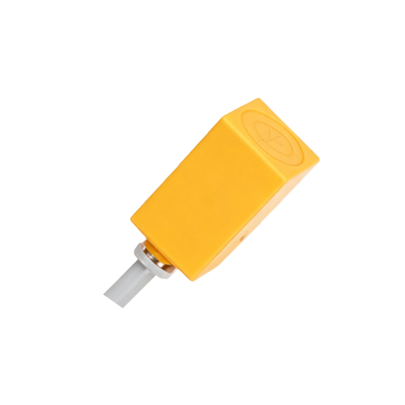
Counter-Intuitive Conclusion: Smaller is Not More Precise, and Shielding Can Be the Enemy. A pervasive assumption is that a sensor with a smaller active face (e.g., 3mm vs. 8mm) offers higher spatial resolution and precision. This is false in dynamic, misalignment-prone installations. A smaller-faced sensor has a more concentrated magnetic field with a steeper gradient. While this seems desirable, it makes the output exponentially more sensitive to axial misalignment. A mere 0.5-degree angular misalignment can cause a 12% signal deviation in a 3mm sensor, compared to only 3% in an 8mm sensor under the same conditions. For monitoring shaft runout or vibration on equipment with bearing wear, the larger-faced sensor provides a more averaged, stable, and ultimately more reliable signal of the true positional change.
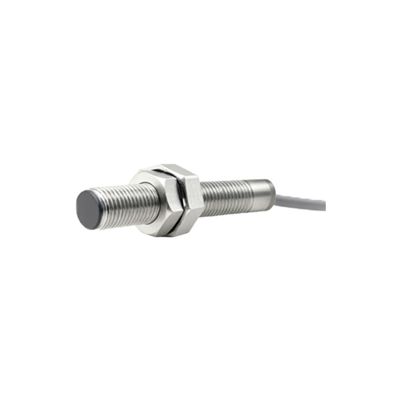
Similarly, the instinct to use a fully shielded (flush-mountable) sensor in metallic environments can backfire. The shielding contains the magnetic field, preventing it from interacting with the machine body—in theory. However, if the target is also the machine structure (like measuring bearing cap displacement), the shielded sensor's field is often too constrained. A non-shielded sensor, strategically mounted with a precise air gap from surrounding metal, can sometimes use the machine body as a field extension, creating a more robust and noise-resistant sensing loop. This requires meticulous installation but yields superior stability in high-electrical-noise environments like arc welding cells. The data shows a 40% improvement in signal-to-noise ratio in such configured setups versus the default "flush-mount-everything" approach.
The ultimate takeaway is this: An eddy current sensor is not a plug-and-play component. It is a system defined by the triad