Forget the pristine data sheets. After two decades of deploying DC inductive and capacitive proximity sensors in steel mills, chemical plants, and automated foundries, I'm here to cut through the marketing fluff. The real world doesn't operate in a 25°C lab. Let's talk about what actually happens when theory meets grit, heat, and vibration.
Experience Correction: The Gritty Truth About Specs
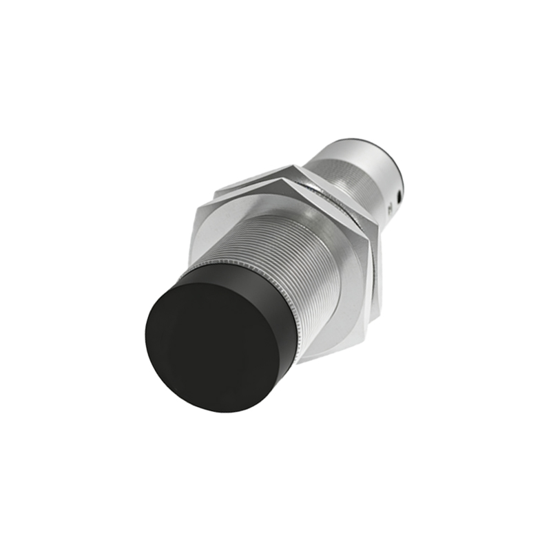
The advertised sensing distance? Assume a 15-25% derating immediately in real-world conditions. For a 10mm standard sensor, plan for 7.5-8.5mm. Why? Surface contamination is the silent killer. A fine, consistent layer of iron dust or conductive coolant mist on an inductive sensor's face permanently reduces its effective range by altering the eddy current damping. No amount of IP67 rating prevents this; it's a physics problem, not an ingress issue. Temperature is the other great liar. A sensor rated for -25 to 70°C might maintain switching function at 65°C, but its repeat accuracy often degrades by over 30%. The oscillator stability drifts, and internal compensation circuits can only do so much. If your application requires precise position detection, the usable upper temperature limit is often 15°C below the stated maximum.
Boundary Conditions: Where DC Proximity Sensors Fail
Deploying them here is professional malpractice. First: Extreme low-speed or static metal detection. A standard inductive sensor detecting a stationary ferrous target can experience temperature drift in the detected signal, leading to false triggers. They are designed for dynamic presence detection. Second: Any environment with high-density plasma or severe arc welding nearby. Stray electromagnetic interference can induce enough voltage in the sensor's output line to ghost-trigger the PLC input, even with shielded cables. Third: Fine, non-ferrous powders (e.g., aluminum, magnesium). Capacitive sensors are often suggested, but these powders coat the active face and can cause permanent activation or a significant shift in the trigger point, creating a massive reliability hole. Fourth: Applications requiring sub-millisecond response time consistency. The internal analog circuit's settling time varies with temperature and supply voltage ripple; for ultra-high-speed counting with micron-level precision, look elsewhere.
Counter-Intuitive Conclusion: Sometimes a "Worse" Sensor is Better
Here’s the heresy: In high-vibration environments, a sensor with a slower response time (e.g., 3ms instead of 1ms) and heavier damping often provides more reliable operation. It effectively low-pass filters the mechanical chatter causing the target to momentarily oscillate in and out of the sensing field. You trade theoretical speed for rock-solid stability, eliminating nuisance pulses that plague "faster" sensors. Another paradox: In highly corrosive washdown (high-pressure caustic cleaners), a sensor with a PTFE or PPS face is superior to standard stainless steel. While less durable mechanically, these plastics are immune to chloride-induced stress corrosion cracking—the number one cause of sudden, catastrophic sensor body failure in food and pharma applications. Finally, on voltage: A 10-30VDC sensor running on a well-regulated 24VDC supply will have a significantly longer lifespan than one on a typical 12VDC line. The higher voltage allows the output transistor to operate in a more linear, less stressed region of its curve, reducing heat generation and electromigration failure. Running at the nominal middle of the range is not always optimal.
The bottom line is this: Selection is no longer about catalog matching. It's about understanding failure modes. Specify for the failure you can tolerate, not the ideal performance you hope for. Your mean time between failures (MTBF) will thank you.