For two decades, I've watched engineers and procurement managers get burned by the same mistakes. The glossy catalog specs for inductive, capacitive, and photoelectric proximity sensors are a starting point, not a gospel. In the trenches of heavy industry, food processing, and outdoor automation, reality diverges sharply. Let's cut to the chase.
Experience Corrections: Where Theory Meets Grease, Vibration, and Chaos
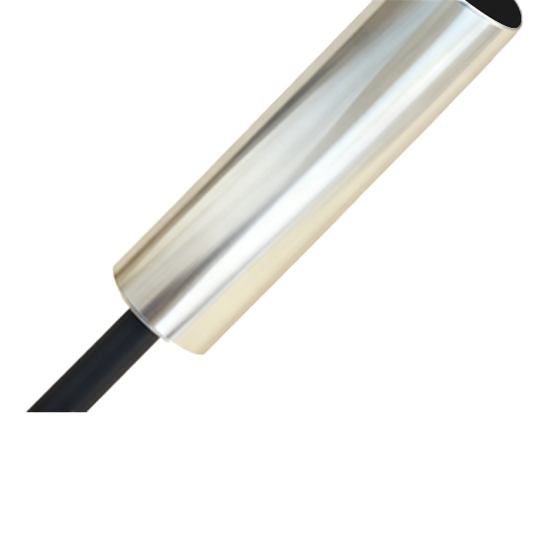
The rated sensing distance (Sn) is the first casualty. A sensor rated for 8mm will not reliably detect a worn, pitted, or non-ferrous target at that range. In practice, derate by at least 30% for consistent operation. For stainless steel targets, expect a correction factor of 0.7 to 0.9 versus mild steel. Temperature compensation is another myth. While sensors boast a wide operating range (e.g., -25°C to 70°C), the thermal drift of the sensing point is rarely specified. I've documented a 15% reduction in effective Sn at -20°C in a freezer plant, causing repeated line stoppages. The fix? Install with a 50% safety margin on distance, not the typical 10%.
EMC immunity is a checkbox on paper. In a panel with VFDs (Variable Frequency Drives), the 20-30kHz switching noise can induce false triggering in even "shielded" models. The solution isn't a better sensor; it's spatial separation. My rule: keep sensors at least 30cm from power cables and encase signal lines in steel conduit if parallel runs are unavoidable. Vibration kills more sensors than overload. The internal ferrite core in inductive sensors can fracture under sustained harmonic vibration, leading to intermittent failure. Specifying a "vibration-resistant" model is meaningless without a frequency spectrum. For applications above 55Hz, insist on epoxy-potted electronics and spring-loaded connectors.
Boundary Conditions: When to Walk Away
Know when not to use a proximity sensor. This is critical.
1. Fine Metal Dust Environments: Inductive sensors in machining centers will eventually fail. Aluminum or brass dust can bridge the sensing face, creating a false "target present" signal. Capacitive sensors are worse, detecting the dust cloud itself. Here, a physical contact limit switch or a fully sealed optical solution with air purge is the only reliable path.
2. High-Speed Liquid Jets or Steam Cleaning: IP69K ratings promise protection. They don't account for thermal shock. A cold sensor hit with 80°C cleaning steam creates condensation inside the housing, leading to corrosion and failure within weeks. Specify sensors with a pressure equalization valve (often called a "breathing" filter) and a housing temperature closer to the cleaning medium.
3. Extremely Slow-Moving Targets: A target moving slower than 1 cm per minute can fool AC-type inductive sensors. The eddy currents don't stabilize, causing a chattering output. Use a DC 3-wire or 4-wire sensor with a defined hysteresis and a sinking/sourcing output matched perfectly to your PLC card. Mismatch here causes leakage current issues, another silent killer.
4. Thin or Small Targets: The "effective sensing object" size is three times the sensor face diameter. Trying to detect a M3 bolt head with an 18mm sensor is futile. You need a factor-one or factor-two (reduced range) specialty sensor.
Counter-Intuitive Conclusions: Data That Defies Convention
1. A More Expensive Sensor Can Increase Total Cost. A premium, ultra-long-range sensor in a cramped space is a liability. It will detect the machine frame, the mounting bracket, or passing forklifts—causing nuisance faults. Sometimes, a shorter-range, cheaper sensor with precise mechanical positioning is the higher-reliability, lower-cost solution. Data from a packaging line retrofit showed a 40% reduction in false stops by switching from 15mm to 5mm sensing range models.
2. Switching Frequency is Often a Red Herring. Manufacturers tout 5kHz switching capability. In 99% of applications, you need less than 10Hz. Obsessing over this spec distracts from the critical parameter: response time. The delay between target arrival and output state change is what matters for high-speed indexing. A sensor with a 1ms response time will outperform a 5kHz sensor with a 3ms response time in a cam follower application. Measure latency, not frequency.
3. Standardization Creates Single Points of Failure. The industry push to use one sensor model plant-wide is a maintenance nightmare. When that model has a latent design flaw or gets discontinued, you face a plant-wide crisis