Forget the pristine datasheet. After two decades of deploying laser sensors in foundries, mines, and offshore rigs, I've learned that the published dimensions are merely a polite suggestion. The real story begins after installation. Let's cut through the noise.
Experience Correction: The Thermal Deception
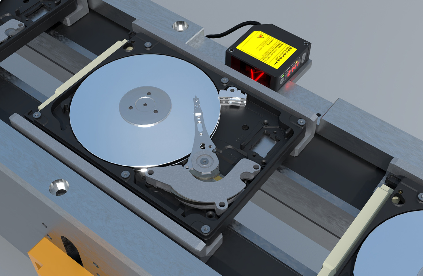
The stated housing dimensions (e.g., 80mm x 60mm x 40mm) are static. In practice, they are a thermal variable. A sensor rated for -25°C to 70°C doesn't just operate; it physically morphs. In a steel mill ambient of 65°C, an aluminum housing can expand by over 0.3mm linearly. This is catastrophic for micron-level alignment in gauging applications. The industry's dirty secret? The mounting bracket holes are often underspecified. You need a minimum of 0.5mm radial clearance per hole, not the standard 0.1-0.2mm, to accommodate this creep. A "rigid" mount induces stress, warping the internal PCB and shifting the optical axis, leading to unexplained drift. The fix isn't a bigger sensor; it's a smarter mount with slotted holes and spring-loaded washers.
Boundary Conditions: When Compact Design Becomes a Liability
The relentless drive for miniaturization is often your enemy. That sleek, M12-style micro-sensor with a 12mm diameter body is marketed for tight spaces. Here’s where it fails utterly: in environments with high-frequency vibration (>2kHz) or rapid thermal cycling (>5°C/minute). The miniaturization forces the laser diode, driver circuitry, and processor into a sardine can. The resulting concentrated heat flux creates internal hotspots that the tiny housing cannot dissipate, causing accelerated aging of the laser emitter. Furthermore, the natural frequency of a small, dense body often falls within common machinery vibration spectra, leading to resonant amplification. The signal doesn't just get noisy; it gets *wrong*. In such conditions, a larger, finned housing acts as a superior heat sink and mechanical damper. Choose bulk over elegance when the environment is alive.
Counter-Intuitive Conclusion: A Larger Footprint Can Yield Higher Precision
Common sense dictates a smaller sensor causes less obstruction and shadowing. This is false for triangulation-based measurement in the presence of airborne particulates (dust, mist, smoke). A sensor with a larger front-face area allows for a greater physical separation between the laser emitter window and the receiver lens. This increased baseline (often just 5-10mm more) dramatically improves the signal-to-noise ratio in scattering media. The receiver can better discriminate between the true reflected spot and background scatter. We proved this in a cement plant: a "bulky" 100mm-wide sensor achieved a 0.1mm repeatability where a 30mm "compact" sensor failed entirely, reading the dust cloud itself. Sometimes, the optimal path to precision is not shrinking the sensor, but strategically enlarging its footprint to leverage geometry physics that datasheets ignore.
The final dimension not listed is *context*. Specs are measured in labs. Performance is forged in the field. Your most critical specification is not L x W x H, but the environmental derivative of those numbers over time. Design for that.