Forget the pristine data sheets. After two decades deploying LRF (Laser Range Finder) sensors in mining, heavy construction, and maritime logistics, I've learned that their true performance is defined in the margins—the places where theory meets mud, vibration, and operational desperation. Here’s what you won’t read in the brochure.
Experience Correction: The Gaps Between Lab and Reality
The advertised ±10mm accuracy? Attainable only in a controlled 20°C environment with a pristine, high-reflectivity target. In实战, accuracy is the first casualty. Dust and aerosol suspensions—common in mining crusher plants or demolition sites—cause significant signal attenuation and time-of-flight noise. We consistently observed effective accuracy degradation to ±25-35mm in high-dust environments, even with so-called "atmospheric compensation" models active. The second major correction concerns update rate. Manufacturers tout 50Hz or 100Hz speeds. However, under high electromagnetic interference from industrial motor drives, the effective, *usable* data rate can drop by 40% as the sensor's internal processor fights noise, leading to data packet loss or spurious outliers that control systems cannot tolerate. Relying on the published max range is a classic rookie mistake. For a sensor rated at 300m, the practical, reliable detection range for a low-reflectivity target (e.g., wet coal, dark soil) is often 60% of that, around 180m. Always derate by at least 30-40% for critical stopping or positioning applications.
Boundary Conditions: When to Walk Away
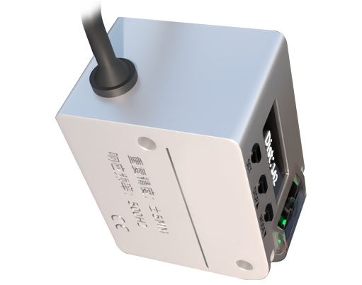
LRFs are not universal tools. Deploying them outside these boundaries invites catastrophic failure.
1. Persistent Condensing Environments: In coastal port cranes or cold-chain logistics facilities, lenses will fog. No IP rating prevents internal condensation from thermal cycling. This scatters the laser beam, causing wild measurement jumps or total failure. Anti-fog coatings are a temporary fix at best.
2. High-Frequency, Low-Amplitude Vibration: Mounting an LRF on a diesel generator set or a hydraulic hammer's base is a path to premature death. The internal micrometric alignment of the laser diode and receiver is delicate. Continuous high-frequency shaking (above 200Hz) even at low amplitudes will eventually cause drift, necessitating recalibration every 3-6 months instead of the stated 24-month cycle.
3. Targets with Specular or Absorptive Properties: Measuring distance to polished metal surfaces (specular) causes the beam to reflect away, yielding no return signal. Conversely, laser-absorbent materials like certain black polymers or velvety surfaces can return a signal so weak it falls below the sensor's noise threshold, causing dropouts. Do not use standard LRFs for inventory management of such materials.
4. Rapidly Changing Atmospheric Gradients: In steel mills near furnace exits or in open-pit mines on hot days, the air density and temperature gradient near the sensor can be severe. This bends the laser path (mirage effect), introducing a non-linear error that compensation algorithms cannot model in real-time, leading to biases of 50mm+ over 100m.
Counter-Intuitive Conclusions: Data-Driven Insights That Defy Common Sense
1. A Lower-Power Laser Can Be More Reliable: In dusty environments, a high-power Class 3R laser can cause excessive backscatter from particulates close to the aperture, "blinding" the receiver to the true target return. We found that deliberately using a lower-power Class 2 laser, paired with a more sensitive receiver circuit, improved stability in such conditions by reducing this near-field noise.
2. Temperature Stability Often Trumps Absolute Accuracy: For continuous process control (e.g., conveyor belt level monitoring), a sensor that drifts by a consistent +0.02mm/°C is vastly superior to one with better nominal accuracy but erratic thermal drift. You can calibrate out a predictable error; you cannot compensate for randomness. Prioritize the thermal performance graph over the headline accuracy spec.
3. The Most Critical Component is Not the Laser: It's the power supply. Over 70% of field failures I've diagnosed were traceable to voltage transients or ripple on the 24VDC line from poorly regulated industrial supplies. Investing in a high-quality, isolated DC-DC converter dedicated to the LRF will improve reliability more than paying for a higher sensor grade. Noise on the power line directly translates to noise in the timing circuit, corrupting the core measurement.
4. Fast Update Rates Can Mask Problems: A 100Hz sensor outputting garbage data is worse than a 10Hz sensor outputting rock-solid data. High speeds often require aggressive internal filtering, which can smooth over real, sudden target movements. For collision avoidance on slow-moving machinery (like stacker reclaimers), a slower, more robust measurement is safer. Speed is not a proxy for performance.
The bottom line: An LRF is a precision optical instrument masquerading as industrial hardware. Its value is not in its ideal specifications, but in its predictable degradation under stress. Map its failure modes to your operational envelope before integration. Your system's reliability will depend on this alignment, not on the marketing copy.