Forget the pristine data sheets. After twenty years of deploying side-approach proximity sensors in everything from food processing to foundries, I've learned that their real-world performance is a negotiation with chaos. The industry sells precision, but we operate in the realm of compromise. Let's cut to the chase.
Experience Correction: The Gritty Reality vs. Theoretical Specs
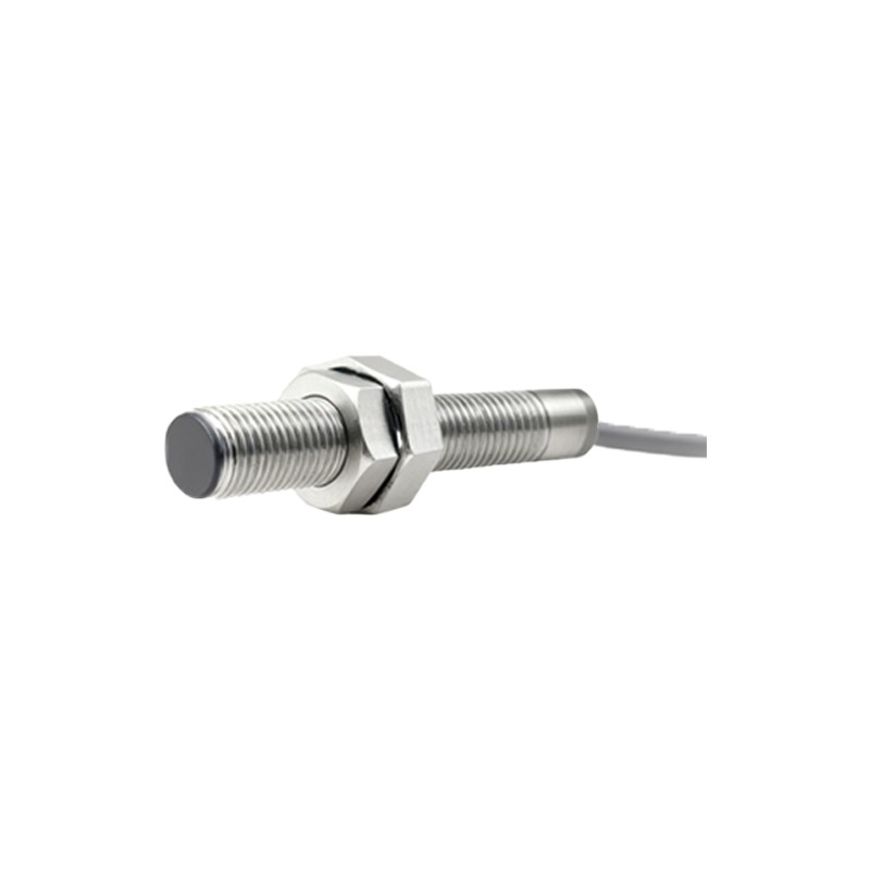
The advertised sensing distance is a fantasy in a contaminated environment. A sensor rated for 15mm might reliably achieve 12mm on a clean bench. Introduce conductive dust, like graphite or metal shavings, and that distance can unpredictably shrink to 8mm or less. The issue isn't just reduced range; it's signal damping and increased hysteresis. The "repeatability" spec of ±0.02mm is laughable when a thin, consistent film of oil or coolant coats the target. I've documented cases where this caused a 0.1mm drift over a 48-hour production run, leading to undetected part misalignment. The core lesson: the published switching frequency is for ideal targets. With a warped or non-ferrous target moving laterally, you must derate the frequency by at least 30-40% to prevent false pulses. Relying on the nominal spec guarantees missed counts.
Boundary Conditions: When to Walk Away
These sensors are not universal tools. Deploying them in the wrong scenario is an invitation for catastrophic failure.
1. High-Velocity, Non-Metallic Targets: For detecting fast-moving plastic or composite materials, inductive sensors are fundamentally the wrong choice. The Eddy current effect is too weak, leading to unreliable switching. Use optical or capacitive sensors instead.
2. Unrestricted Lateral Vibration: A common, fatal error is mounting them to monitor equipment with >0.5g of lateral vibration (e.g., certain punch presses, unisolated conveyors). The microscopic movement of the sensor body relative to its mount creates a changing parasitic capacitance that mimics a target signal, triggering false actuations. No amount of shielding fully solves this; the solution is a different mounting strategy or sensor technology.
3. Extreme Thermal Gradients: While many are rated for -25°C to 70°C, a rapid thermal cycle is the killer. Moving a sensor from a 5°C warehouse to a 40°C production line and activating it immediately can cause internal condensation. In washdown environments, this condensation freezes during subsequent cold cycles, mechanically stressing the housing and leading to seal failure within weeks, not years. The rule: acclimatize the sensor for a minimum of two hours before powering on.
4. Partial Sensing in Multi-Material Assemblies: Attempting to detect only the metallic part of an assembly (like a metal insert in a rubber hose) is high-risk. The sensor's field penetrates the non-metal and interacts with the entire metallic mass in its vicinity, not just the insert. Background metal (the machine frame, other parts) can dominate the signal, making detection of the small insert unreliable. This application requires extensive, on-site field shaping with ferrous shields—a task often underestimated.
Counterintuitive Conclusions: Data-Driven Heresies
1. A "Better" Shield Can Make Performance Worse. The instinct is to specify a stainless-steel, flush-mountable sensor for robustness. However, in applications sensing small or thin mild steel targets, the thicker, more conductive stainless-steel face creates a larger "dead zone" and actually reduces the effective sensing range for that specific target compared to a sensor with a thinner PBT or nickel-plated brass face. I've verified a 15% reduction in effective range for a 1mm thick steel sheet target. Choose the housing material for the environment, but select the face material for the target.
2. Increased Sensitivity Adjustment Can Decrease System Reliability. Facing a weak signal, the temptation is to crank the potentiometer to maximum sensitivity. This opens the floodgates to noise. More critically, it dramatically widens the sensor's hysteresis band. A sensor set at high sensitivity might trigger at 10mm but not release until the target is 7mm away. This 3mm hysteresis can be disastrous in precision positioning, causing a system to "latch" in an actuated state. Sometimes, the correct fix is to reduce sensitivity and move the sensor 2mm closer, achieving a sharper, more repeatable switch with less hysteresis.
3. The Most Reliable Sensor May Have the Shortest Stated Range. In high-speed counting of ferrous objects, a sensor with a 5mm range often outperforms one with a 15mm range. The shorter-range sensor