Forget the datasheet. After two decades of deploying proximity sensors in environments ranging from automotive paint shops to offshore drilling rigs, I've learned that the real specification is written by grit, temperature extremes, and electromagnetic chaos. This is not an introduction. This is a dissection.
Experience Corrections: The Gap Between Lab and Reality
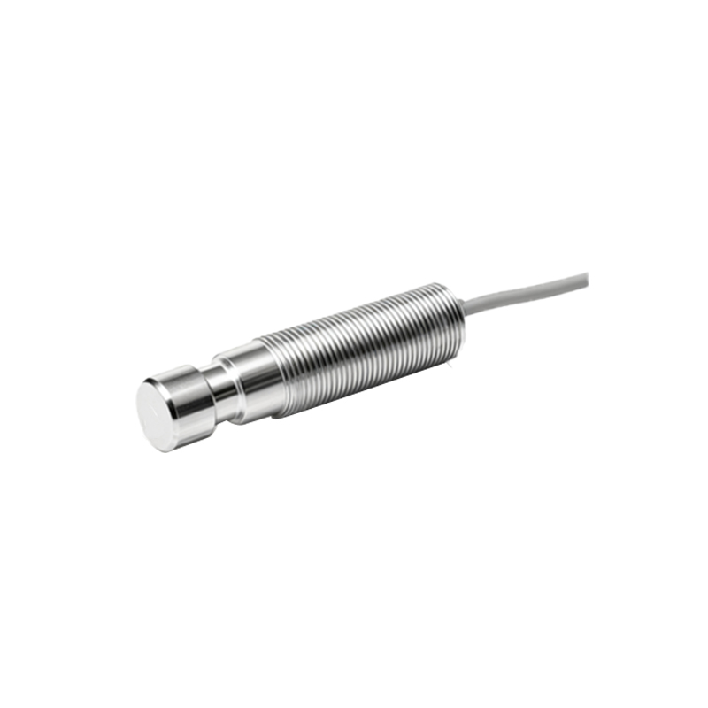
Theoretical sensing ranges and repeatability are laboratory fantasies. Take the ubiquitous 12mm inductive sensor, often rated for a 4mm nominal range. In practice, with a perfectly aligned, mild steel target? You'll get 4mm. Introduce a worn, pitted, or galvanized target, and effective range degrades by 30-40%. The "standard" target (1mm thick, Fe360) is a ghost in the real world. More critically, the temperature coefficient is a silent killer. A sensor rated for 0-70°C might maintain its switching point within ±10% in the brochure. In a metal stamping plant where ambient temperatures hit 45°C and the sensor body conducts heat from machinery, that drift can exceed 15%, causing late or early triggering. I've documented cases where a 5°C increase in core temperature led to a 0.1mm shift in actuation point—enough to cause a misfeed in high-precision assembly.
EMC immunity is another grand illusion. CE marking is a baseline, not a guarantee. In a facility with variable frequency drives (VFDs) controlling motors, the high-frequency switching noise can induce false pulses in a sensor's output, even with shielded cables if the grounding is "daisy-chained." I've solved more "ghost signals" by implementing star-point grounding and ferrite clamps than by replacing sensors. The takeaway: The rated operating voltage (10-30V DC) means nothing if your power supply line carries high-frequency noise. Ripple should be under 50mV, but I've measured over 500mV in "stable" systems.
Boundary Conditions: Where It Will Fail
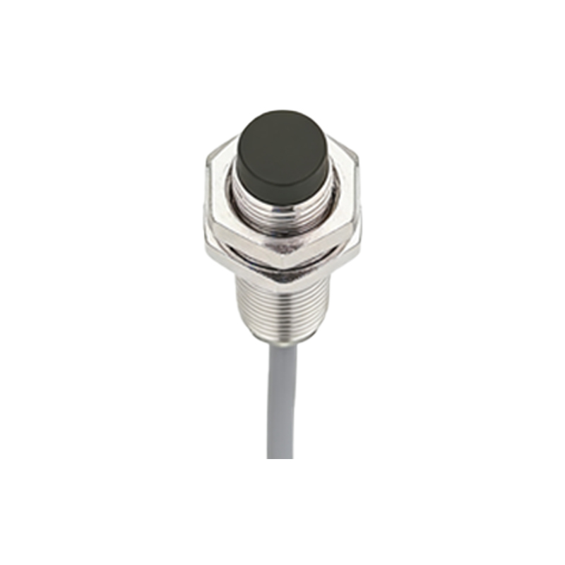
Proximity sensors are not universal tools. Here are the scenarios where they become liabilities:
1. Non-Ferrous Metal Detection with Inductive Sensors: Using a standard inductive sensor on aluminum or copper is an invitation for inconsistency. The sensing range can drop to as little as 20% of the nominal range. Worse, the detection is highly sensitive to alloy composition and temperature. A batch of 6061 aluminum versus 7075 can show a 15% variance in trigger point. In these applications, if you're not using a factor-1 sensor specifically designed for non-ferrous metals, you are building in a process fault.
2. High-Sludge or Conductive Contaminant Environments: In pulp and paper or wastewater treatment, capacitive sensors are often chosen for level detection. However, if the conductive medium (e.g., slurry) coats the sensor face, it becomes part of the sensing field, causing a permanent "on" state. Heated or mechanically cleaned faces are not luxuries here; they are necessities. Failure to implement them leads to overflow events.
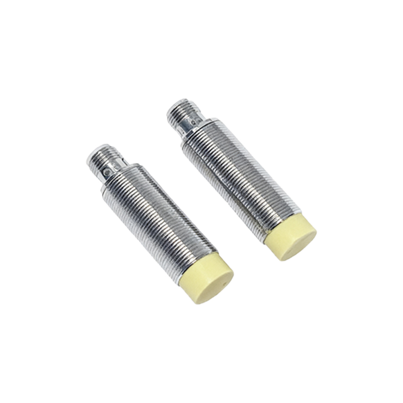
3. Ultra-High-Speed Counting: You have a sensor with a 1kHz response frequency. Theoretically, it can count 1000 items per second. In practice, for reliable counting of small, fast-moving parts (e.g., pharmaceutical capsules), you must derate by at least 50%. Target presentation time must be greater than the sensor's response time plus the controller's input delay. I've seen systems fail because they relied on the max frequency rating without accounting for target size and vibration-induced bounce, which the sensor interprets as multiple counts.
4. Extreme Pulsed Magnetic Fields: Near large spot welders or MRI machines, the intense, pulsed magnetic fields can saturate the core of an inductive sensor, causing a temporary loss of sensing ability (latch-up) for several milliseconds post-pulse. This is a catastrophic failure mode for synchronization.
Counterintuitive Conclusions: Data That Defies Common Sense
1. A More Expensive Sensor Can Be Less Reliable in Simple Apps: A high-precision, laser-adjusted sensor with 0.1% repeatability is overkill for detecting a garage door's closed position. Its sophisticated circuitry is often more susceptible to power supply noise and thermal drift in an unconditioned environment than a rugged, less precise, analog-tuned unit. The complexity introduces failure modes where none needed to exist. Sometimes, "dumber" is more robust.
2. Increased Sensing Distance Can Reduce System Stability: In mechanical design, there's a temptation to specify a sensor with a longer range to accommodate greater