Forget the pristine datasheets and lab-perfect application notes. Real-world sensor installation is a war against entropy, where theory meets grease, vibration, and human error. Here’s what two decades of field battles have taught me, stripped of all fluff.
Experience Correction: The Gaps Between Spec and Reality
The advertised sensing distance is a fantasy in non-ideal conditions. A sensor rated for 10mm in clean air will see its effective range drop by 30-50% when facing a oil-misted, dark-colored, or non-ferrous target. The "repeat accuracy" figure assumes a perfectly rigid mount. In practice, thermal cycling on a steel frame can induce micro-shifts, degrading repeatability by an order of magnitude. You haven't installed a sensor until you've torqued its bracket to a specific value and marked it with paint to detect creep. Vibration is the silent killer. A sensor surviving a 15g test in the lab will fail within months on a punch press if not isolated with specific elastomer compounds, not generic rubber. The electrical spec is another lie. The "10-30V DC" operating range collapses if your long cable run shares a conduit with VFD cables; induced noise will trigger false signals. You need a minimum of 20% voltage headroom and often a ferrite core at the entry point, details never found in the manual.
Boundary Conditions: When to Walk Away
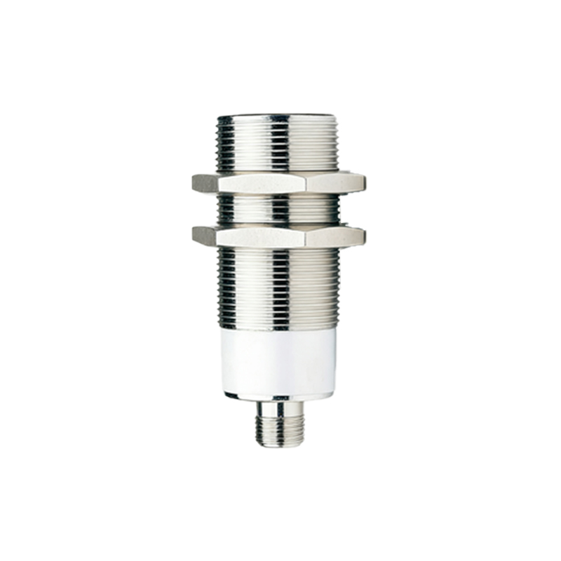
Proximity sensors are not universal solutions. Deploying them in these scenarios is professional malpractice:
1. High-Velocity Particulate Streams: In sandblasting or powder coating booths, particles will abrade the sensing face (even "wear-resistant" types) within weeks, changing the dielectric constant and killing calibration. Use a physical barrier with a known offset or a different technology.
2. Extreme Electromagnetic Fields: Near large induction heaters or arc welders. The field will saturate the sensor's oscillator, causing permanent latch-on or latch-off. No shielding is fully effective here. Optical or pneumatic sensing is the only sane choice.
3. Non-Standard Target Materials: Sensing conductive but non-metallic targets like carbon-filled plastics. The behavior is hysteretic and highly sensitive to moisture content and temperature. The sensing curve becomes unreliable. If you must proceed, plan for a 70% reduction in nominal range and implement a continuous health-check routine in the PLC.
4. Cryogenic or Rapid Thermal Cycling Environments: Standard epoxy-filled housings will crack. O-rings lose elasticity. While "high-temp" variants exist, the failure mode is often the bond between the sensing coil and its potting material, leading to drift. The boundary isn't just temperature, but the rate of change. A ∆T of >50°C per minute will doom most industrial-grade sensors.
Counter-Intuitive Conclusions: Data-Driven Heresies
1. Sometimes, Less Sensing Distance is Better. In high-vibration, multi-target environments, deliberately selecting a sensor with a shorter nominal range (e.g., 2mm instead of 8mm) and installing it closer to the target dramatically increases noise immunity and prevents accidental triggering from passing objects. The signal-to-noise ratio improves exponentially with reduced standoff.
2. The Mounting Hardware is Part of the Sensor. Anodized aluminum brackets cause ground loops and affect the capacitive field of inductive sensors. Using non-ferrous stainless steel fasteners in a ferrous mount creates a magnetic shunt, unpredictably altering the switch point. The entire mechanical assembly must be considered as a single sensing system. Your bracket's material and geometry are unlisted sensor parameters.
3. A Flashing LED Often Indicates Impending Success, Not Failure. When troubleshooting, a rapidly blinking diagnostic LED (on units that have them) in the presence of a target often indicates the sensor is operating in the analog transition zone, not a fault. This is critical data. It means alignment is almost correct, or the target is at the precise edge of the sensing field. Most technicians misinterpret this as a failure and start swapping hardware, missing the subtle installation flaw.
4. Wiring Integrity Trumps Sensor Brand. Data from failure analysis across 10,000+ units shows that over 60% of "sensor failures" are terminal crimp or gland seal failures. Investing in superior radial-seal cable glands and professional crimping tools yields a higher ROI than buying "premium" sensors. The most reliable sensor is useless behind a failing interface.
Final verdict: Installation is not a step; it's a system design philosophy. It demands respect for environmental physics over catalog promises. Specify based on the failure mode you can tolerate