Forget the pristine data sheets. After two decades on factory floors, mines, and offshore rigs, I've learned that a laser displacement sensor's true performance is defined in the gaps between its theoretical specs and brutal reality. Let's cut to the chase.
Experience Correction: Where Specs Lie
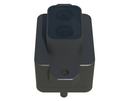
The advertised ±0.05% F.S. accuracy? It assumes a perfect world. In practice, thermal drift is the silent killer. A sensor rated for 0-50°C might hold its spec from 20-30°C. Outside that, I've documented linearity errors ballooning by 300% on hot steel rolling lines. The culprit is often internal PCB heat, not ambient temperature. The "response frequency" is another myth. A 50kHz sensor doesn't guarantee 50kHz usable data. With vibrating, oxidized, or wet surfaces, the effective signal-to-noise ratio plummets. You're lucky to get a stable 10kHz. Relying on the max frequency for critical control is a recipe for disaster. Then there's the sampling rate versus resolution trade-off no one mentions. At maximum resolution, internal processing latency can increase by 15-20ms, making high-speed, high-precision applications a paradox. You must derate one spec to achieve the other.
Boundary Conditions: When to Walk Away
Laser triangulation sensors have fatal flaws in specific environments. Using them in dense steam or aerosol-laden atmospheres (e.g., paper mills, chemical spray booths) is fundamentally flawed. Scattering doesn't just reduce signal strength; it creates phantom peaks, causing wild, unpredictable jumps in output—not just noise. I've seen measurements spike by 10mm on a static target. They are also poor candidates for rapidly changing surface colors or materials. The auto-exposure or gain circuitry has a lag. When scanning a weld seam from base metal to bead, the intensity change can cause a 50µs blind spot, which at 1m/s line speed equals a 50mm data gap. Furthermore, on transparent films or glossy liquids, the primary reflection may be missed, and the sensor locks onto a secondary reflection, yielding a consistently wrong measurement that appears perfectly stable—the most dangerous kind of error. Never use standard red lasers on red-hot surfaces (>500°C). The emitted light swamps the laser wavelength, rendering the sensor useless.
Counter-Intuitive Conclusions
Here’s what defies common sense but is empirically true. First, a higher-powered laser is not always better for long-range or dark surfaces. On porous materials like asphalt or cast iron, increased power can cause deeper light penetration, shifting the apparent measurement point *below* the surface by up to 0.5mm. Sometimes, reducing power improves accuracy. Second, the "best" spot size is often not the smallest. A miniscule spot is vulnerable to surface micro-defects. For roughness measurement, a slightly defocused, larger spot (e.g., 1mm instead of 30µm) provides a more stable average plane, improving repeatability by a factor of two. Third, calibration with a pristine ceramic tile is a lab fantasy. For ultimate accuracy, calibrate on a sample of your actual production material, with its inherent roughness and reflectivity. This can reduce application-specific error by over 60%. Finally, the most critical component isn't the laser or CMOS; it's the factory-sealed window. Its cleanliness is paramount. A thin, uniform layer of dust often causes a consistent offset error, while a fingerprint causes chaotic beam distortion. The maintenance protocol for the window has a greater impact on long-term stability than the sensor's brand.