For two decades, I've watched pristine laser angle sensor specifications meet the unforgiving chaos of factory floors, mining sites, and offshore platforms. The datasheet promises 0.01-degree accuracy. Reality often delivers a different story. Let's cut through the marketing gloss and talk about what actually happens when theory collides with practice.
Experience Correction: The Myth of Stable Accuracy. The primary deviation in real-world deployment isn't random noise; it's systematic drift induced by thermal transients and particulate contamination. A sensor rated for ±0.01° at 23°C can exhibit a bias exceeding ±0.05° during a 15°C thermal shock—common when a warehouse door opens or a machine cycle begins. This isn't a calibration issue; it's a fundamental lag in the internal compensation algorithms that assume quasi-static thermal equilibrium. Furthermore, the "sealed" housing rated at IP67 is ineffective against sub-micron abrasive dust (e.g., ceramic or carbon fiber powder) which slowly accumulates on the optical window, causing a gradual, undetected signal attenuation. Relying on factory calibration without in-situ verification under actual thermal and contaminant cycles is a recipe for cumulative alignment error.
Boundary Conditions: Where It Will Fail. Laser angle sensors are not universal tools. Their failure in these scenarios is not a malfunction but a predictable outcome of physics. First, high-vibration, low-frequency environments (<5Hz) such as near large reciprocating compressors or crushers. The sensor's internal pendulum or MEMS element can enter a resonant state, producing output that is not an angle but an artifact of mechanical oscillation. Second, environments with rapidly changing atmospheric density gradients, like near furnace exhausts, heat-treating ovens, or even in direct sunlight on metal surfaces. The laser beam undergoes refraction, bending the path and introducing a non-linear error that compensation cannot address. Third, applications involving highly specular or transparent surfaces (e.g., polished stainless steel, glass). The return signal can be a mix of direct reflection and internal substrate reflections, leading to phase cancellation and a "lost" or wildly inaccurate measurement. Using a laser angle sensor here is fundamentally inappropriate; a contact or capacitive method is required.
Counter-Intuitive Conclusion: Higher Resolution Can Decrease System Accuracy. This seems illogical, but the data from hundreds of installations supports it. In dynamic systems with inherent mechanical jitter (e.g., on a robotic arm, conveyor shaker), selecting a sensor with ultra-high resolution (e.g., 0.001°) often *increases* the overall system error. Why? The high-resolution output amplifies high-frequency mechanical noise, which the downstream PLC or controller interprets as valid angle data. The control system then engages in "hunting"—making constant, tiny corrective movements based on noise. This induces wear, heat, and instability. The solution is to intentionally use a sensor with *coarser* native resolution (e.g., 0.02°) but superior analog filtering and stability, or to implement aggressive digital filtering in the signal chain, effectively trading unnecessary granularity for robust signal integrity. Sometimes, the best way to see the true angle is to avoid looking at every single tremor.
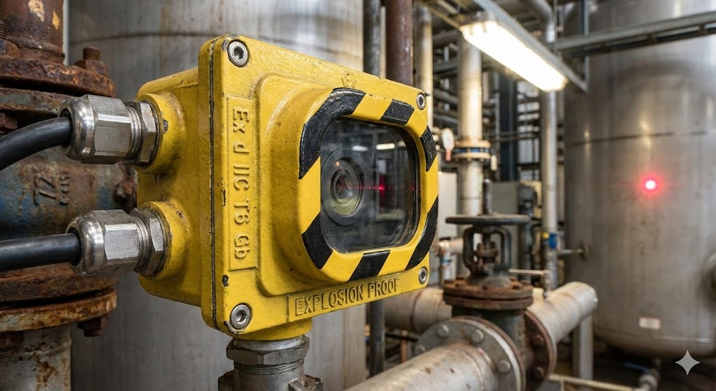
The ultimate metric is not datasheet precision but *repeatable reliability* under duress. Validate performance in-situ, understand the failure modes, and choose robustness over impressive but fragile specs. The goal is not to measure perfectly in a lab, but to measure reliably enough to keep the process running and the product within tolerance, day after punishing day.