Building a proximity sensor circuit is a fundamental project for electronics enthusiasts, offering practical applications in automation, robotics, and security systems. Unlike complex commercial sensors, a DIY circuit provides a hands-on understanding of detection principles and component integration. This guide walks through creating a basic infrared (IR) proximity sensor, emphasizing simplicity and functionality without relying on pre-assembled modules.
The core of this circuit is an IR LED and a photodiode or phototransistor. The IR LED emits infrared light, which reflects off nearby objects and is detected by the photodiode. The intensity of reflected light correlates to the object's distance, triggering an output signal. Key components include an IR LED (e.g., 5mm, 940nm), a phototransistor (like the L14G2), a comparator IC (such as the LM393), resistors (values detailed below), a potentiometer for sensitivity adjustment, and a power supply (3–5V DC).
Start by placing the IR LED and phototransistor side-by-side on a breadboard, ensuring they are parallel and unobstructed. Connect the IR LED's anode to a 100-ohm resistor linked to the positive supply; its cathode goes to ground. This setup limits current to prevent burnout. For the phototransistor, connect its emitter to ground and its collector to a 10k-ohm pull-up resistor tied to the positive rail. The junction between the phototransistor's collector and the pull-up resistor forms the detection node, where voltage changes with reflected IR light.
Next, integrate the LM393 comparator. Link the detection node to the comparator's non-inverting input (pin 3). Use a voltage divider—with a potentiometer (e.g., 10k ohms) between the supply and ground—to set a reference voltage on the inverting input (pin 2). Adjusting the potentiometer fine-tunes the detection threshold. The comparator's output (pin 1) switches high or low based on whether the detection voltage exceeds the reference. Add an output indicator, like an LED with a 220-ohm resistor, to pin 1 for visual feedback.
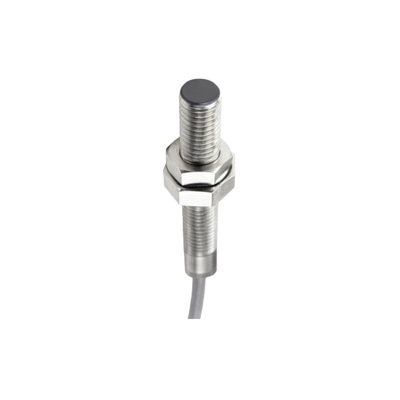
Power the circuit and test it. Move an object (non-reflective surfaces work best) within 5–20 cm of the sensors. The output LED should illuminate when the object is close. If unresponsive, check connections, ensure the IR LED emits light (use a phone camera to see IR glow), and calibrate the potentiometer. Noise from ambient light can be mitigated by enclosing the sensors in a tube or using modulated IR signals with additional circuitry.
This basic design can be expanded. For longer range, add a lens to focus IR light. To drive relays or microcontrollers, buffer the output with a transistor. For precise distance measurement, replace the comparator with an analog-to-digital converter and microcontroller. Always double-check polarity, avoid short circuits, and use a stable power source to prevent damage.
In summary, constructing a proximity sensor circuit demystifies sensor technology, offering a customizable, cost-effective solution. With practice, you can adapt it for touchless switches, obstacle detection, or interactive displays, bridging theoretical electronics and real-world innovation.