Proximity sensors are integral components in modern automation and electronic systems, designed to detect the presence or absence of objects within a specific range without physical contact. Their functionality relies heavily on correct pin configuration, which ensures proper power supply, signal output, and communication with control units. This article delves into the common pin layouts of proximity sensors, explaining their roles and how to connect them effectively in circuits.
Typically, proximity sensors feature three to four pins, though some advanced models may include additional pins for enhanced features like diagnostics or adjustable sensing ranges. The most basic three-pin configuration includes power (V+), ground (GND), and output (OUT) pins. The power pin, often labeled V+ or Vcc, connects to a positive voltage source, usually ranging from 5V to 24V DC, depending on the sensor model. It supplies the necessary energy for the sensor to operate. The ground pin, marked GND or 0V, completes the electrical circuit by linking to the negative terminal of the power supply. This pin is crucial for stabilizing the sensor's internal electronics and preventing electrical noise interference. The output pin, designated OUT or Signal, transmits detection data to external devices such as microcontrollers, PLCs, or relays. When an object is detected within the sensing range, the output pin switches states—either from high to low voltage (NPN type) or low to high (PNN type)—triggering a response in the connected system.
For sensors with four pins, the additional pin often serves as a complementary output or a diagnostic function. In some cases, it provides a second output channel for redundancy or different signal types, such as analog voltage or current outputs for distance measurement. Other models include a pin for adjusting sensitivity or setting hysteresis, allowing users to fine-tune the sensor's response to environmental conditions. It's essential to consult the manufacturer's datasheet for precise pin definitions, as variations exist across brands and applications. Incorrect wiring can lead to sensor malfunction, reduced accuracy, or even permanent damage.
When integrating a proximity sensor into a circuit, start by identifying the pin layout through markings on the sensor body or its documentation. Use a multimeter to verify voltage levels if needed. Connect the power and ground pins first to energize the sensor, then link the output pin to the input of your control device. Ensure all connections are secure and insulated to avoid short circuits. For industrial setups, consider using shielded cables to minimize electromagnetic interference, especially in environments with heavy machinery. Testing the sensor with a target object before full deployment helps confirm proper operation and alignment.
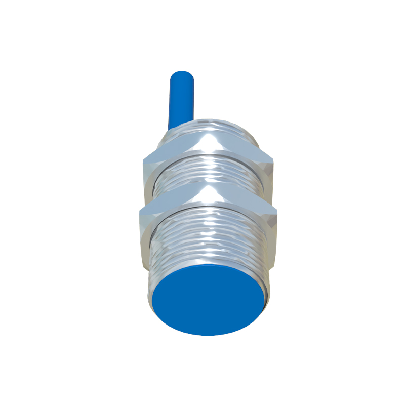
Common issues related to pin connections include reversed polarity, where power and ground are swapped, causing the sensor to fail or overheat. Another problem is incorrect output loading, where the connected device draws too much current, potentially damaging the sensor's output circuit. To avoid these, always adhere to the rated specifications for voltage, current, and load resistance. Additionally, environmental factors like moisture or dust can affect pin conductivity, so choose sensors with appropriate IP ratings for your application.
In summary, understanding the pin configuration of proximity sensors is key to their successful implementation. By following wiring guidelines and accounting for sensor type and environment, users can achieve reliable detection and enhance system performance. Whether in automotive, manufacturing, or consumer electronics, proper pin management ensures these sensors operate efficiently, contributing to smarter and safer automated solutions.