Proximity switch sensors are widely used in industrial automation, robotics, and safety systems for non-contact detection of objects. Understanding the circuit diagram of a proximity sensor is essential for engineers, technicians, and hobbyists working with electronic control systems. This article provides a detailed explanation of a typical proximity switch sensor circuit, covering its components, working principle, and practical applications.
A standard proximity switch sensor circuit consists of several key parts: an oscillator, a demodulator, an amplifier, and an output stage. The oscillator generates a high-frequency electromagnetic field using a coil or capacitive element. When a metallic or conductive object enters this field, eddy currents are induced, causing a change in the oscillator's amplitude or frequency. This change is detected by the demodulator, which converts it into a DC signal. The signal is then amplified by the amplifier to a usable level, triggering the output stage—usually a transistor or relay—to switch on or off.
In inductive proximity sensors, the oscillator circuit often includes an LC tank circuit with a coil (L) and capacitor (C). The coil acts as the sensing element, and its inductance changes when a metal object approaches. This alters the resonant frequency, which is monitored by the circuit. For capacitive proximity sensors, the circuit uses a capacitive plate to detect changes in capacitance caused by non-metallic objects, such as plastics or liquids. The circuit diagram for capacitive types includes a capacitor in the oscillator network, with sensitivity adjustments for different materials.
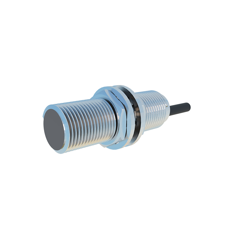
The output stage is crucial for interfacing with other devices. Common configurations include NPN or PNP transistor outputs for DC sensors, and relay outputs for AC sensors. In the circuit diagram, the output is typically labeled with terminals for power supply (Vcc and GND), output signal (OUT), and sometimes a diagnostic LED. For example, a three-wire DC sensor circuit shows connections for positive voltage, ground, and output, while a two-wire AC sensor integrates the output in series with the power line.
Design considerations for proximity sensor circuits include power supply stability, noise immunity, and environmental factors. Shielding and filtering components, such as resistors and capacitors, are often added to reduce electromagnetic interference. The circuit diagram may also include protection diodes to prevent voltage spikes and ensure longevity. When building or troubleshooting, refer to the manufacturer's datasheet for specific values and layout guidelines.
Applications of proximity switch sensors range from simple object detection in conveyor belts to complex positioning in machinery. In automotive systems, they monitor wheel speed for anti-lock braking. In consumer electronics, they enable touchless controls. Understanding the circuit diagram helps in customizing sensors for specific needs, such as adjusting sensing range or output type.
In summary, a proximity switch sensor circuit diagram illustrates the interaction of electronic components to achieve reliable non-contact sensing. By studying the diagram, one gains insights into sensor operation, enabling effective implementation and maintenance in various technical fields.