Reed switch sensors, often referred to as magnetic reed switches, are fundamental components in countless applications, from simple door/window alarms to sophisticated industrial automation and automotive systems. Their operation is elegantly simple: two ferromagnetic, nickel-iron reed contacts are hermetically sealed within a glass tube filled with an inert gas. When an external magnetic field of sufficient strength is applied, the reeds attract each other, making contact and closing the circuit. Removing the magnetic field allows the reeds' natural spring tension to separate, breaking the circuit. Selecting the right reed sensor hinges on a deep understanding of its key specifications, which dictate its performance, reliability, and suitability for a given task.
The cornerstone specification is the Operate Point (Pull-In Value), denoted as AT (Ampere-Turns). This is the minimum magnetomotive force required to reliably close the reed contacts. It is typically measured in Ampere-Turns (A·T) or millitesla (mT). A lower operate point indicates a more sensitive switch, requiring a weaker magnetic field to activate. Conversely, a higher operate point offers greater immunity to stray magnetic fields, reducing the risk of false triggering. Engineers must balance sensitivity with environmental magnetic noise.
Closely related is the Release Point (Drop-Out Value), the magnetomotive force at which the contacts reliably open once the magnetic field is reduced. The difference between the Operate Point and the Release Point is the Hysteresis. This built-in gap prevents contact "chatter" – rapid opening and closing – when the sensor is near its activation threshold, ensuring a clean, single switching event. A well-defined hysteresis is critical for stable operation in applications where the magnet may move slowly or vibrate near the sensor.
Contact Rating is a critical safety and longevity parameter. It defines the maximum voltage and current the closed contacts can safely switch. Exceeding these ratings leads to arcing, which damages the contact surfaces, increases resistance, and ultimately causes premature failure. Ratings are specified for both resistive (e.g., 10W, 100V, 0.5A) and inductive loads (which are harder to switch due to voltage spikes). For low-power signal applications (dry circuit), a low-current rating is specified to ensure reliable operation with tiny currents.
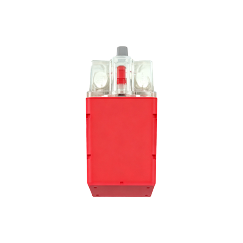
Contact Form describes the switching configuration. The most common types are Form A (Normally Open, SPST), Form B (Normally Closed, SPST), and Form C (SPDT or changeover), which combines both NO and NC contacts in one package. Form C offers great flexibility for control logic.
Switching Time is the interval between the application (or removal) of the magnetic field and the electrical closure (or opening) of the contacts. It is extremely fast, typically in the range of 0.1 to 2 milliseconds. While fast for many applications, this parameter is vital in high-speed counting or timing circuits.
Breakdown Voltage is the maximum voltage the open contacts can withstand without arcing across the gap. This is important for ensuring isolation in high-voltage circuits. Insulation Resistance measures the resistance between the open contacts and between the contacts and the sensor casing, indicating the quality of the glass seal and internal cleanliness.
Operational Life is the guaranteed number of reliable switching cycles. It varies dramatically based on the load. Switching rated loads at low power (e.g., 5V, 10mA) can yield hundreds of millions of cycles. Switching inductive or high-power loads near the maximum rating significantly reduces life expectancy due to contact erosion.
Physical and Environmental Specifications are equally crucial. The Glass Length and Diameter affect the magnetic sensitivity and mechanical robustness. Termination Style (leaded, surface mount, screw terminal) determines mounting method. Operating Temperature Range specifies the ambient conditions the sensor can endure without degradation of specs or seal integrity. The hermetic seal protects against dust, moisture, and corrosion, but the specified Ingress Protection (IP) Rating for the overall assembly must be considered.
When selecting a reed sensor, start by defining the application's electrical needs (voltage, current, load type) and environmental conditions. Choose an operate/release point that works reliably with your chosen magnet and its expected travel path. Always derate the contact rating—using a switch at 50-70% of its maximum rating dramatically improves longevity. For harsh environments, specify sensors with high-temperature glass and robust lead seals. Consulting detailed manufacturer datasheets, which provide characteristic curves and application notes, is indispensable for making an optimal, reliable, and cost-effective selection.