In the realm of industrial automation, robotics, and advanced measurement systems, the precise alignment and integration of laser sensors stand as a critical determinant of system performance and data accuracy. This process, often referred to as laser sensor docking or interfacing, extends far beyond simple physical mounting. It encompasses a meticulous orchestration of mechanical positioning, optical calibration, electronic synchronization, and software configuration to ensure the sensor operates as a seamless, high-fidelity component within a larger ecosystem.
The foundation of successful laser sensor integration begins with mechanical alignment. This involves securing the sensor in its designated mount or housing with extreme precision to minimize vibrational artifacts and thermal drift. The goal is to achieve a stable, repeatable physical reference point. For applications involving triangulation sensors, line lasers, or time-of-flight (ToF) modules, even a micron-level deviation in the mounting angle or position can translate into significant measurement errors downstream. Engineers often employ precision stages, adjustable brackets, and alignment fixtures featuring fine-threaded screws for micro-adjustments. The use of spirit levels, dial indicators, and laser alignment tools themselves is common during this phase to verify perpendicularity and parallelism relative to the target plane or reference datum.
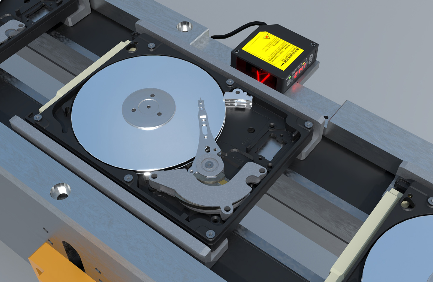
Following mechanical stability, optical alignment becomes paramount. This step ensures the laser beam's path, focus, and detection field of view are optimally configured for the specific task. For instance, aligning a confocal chromatic sensor requires precise positioning so its focused beam spot falls exactly on the target measurement area. Similarly, for laser profilometers that scan a line across a surface, the line must be perfectly oriented and in focus across its entire length. Technicians adjust lens positions, apertures, and sometimes employ intermediary optical elements like beam splitters or mirrors to direct the laser path. This process is frequently guided by real-time feedback from the sensor's own output or an auxiliary camera system, allowing for iterative refinement until the signal strength, spot shape, or line uniformity meets stringent specifications.
The electronic and signal interfacing layer is the nervous system of the integration. A laser sensor's raw analog signals or digitized data must be accurately transmitted to a controller, such as a Programmable Logic Controller (PLC), Industrial PC (IPC), or dedicated data acquisition (DAQ) card. This involves selecting the correct communication protocol—common choices include analog voltage/current loops (0-10V, 4-20mA), digital I/O for triggering, and serial protocols like RS-422/485. Increasingly, industrial Ethernet protocols (EtherCAT, PROFINET, EtherNet/IP) and fieldbus systems are used for high-speed, deterministic data transfer in synchronized multi-sensor networks. Proper wiring, shielding against electromagnetic interference (EMI), and adherence to cable length specifications are crucial to prevent signal degradation, noise, or latency. Power supply considerations, including voltage stability and current capacity, are equally vital to ensure consistent sensor operation.
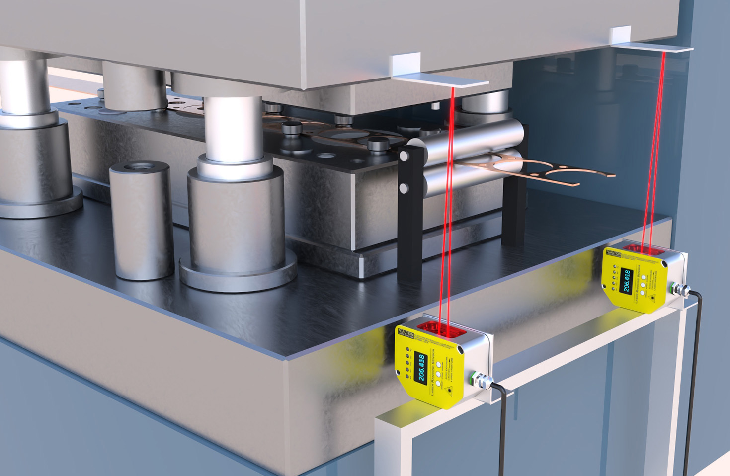
Software configuration and calibration finalize the docking process. Here, the sensor is "taught" its operational context through software provided by the manufacturer or integrated into a larger SCADA/MES platform. Key tasks include setting measurement ranges, defining output scaling (e.g., engineering units like millimeters or microns), configuring filtering algorithms to reduce noise, and establishing trigger conditions. Calibration is performed using certified reference standards—such as gauge blocks for distance sensors or standardized roughness samples for surface inspection sensors—to create a translation model between the sensor's raw output and true physical values. This step often involves generating and applying linearization or correction tables to account for any non-linearities in the sensor's response across its working range.
The challenges in laser sensor docking are multifaceted. Environmental factors like ambient light, dust, oil mist, or temperature fluctuations can severely impact optical sensors. Mitigation strategies involve using sensors with specific spectral filters (e.g., narrow-band lasers with matched filters), installing protective enclosures with clean air purges, or applying protective coatings on optics. In dynamic systems, such as those on robotic arms, the alignment must withstand accelerations and path repetitions without loosening, necessitating robust locking mechanisms and periodic re-verification schedules.
Ultimately, the precision alignment and integration of a laser sensor is a multidisciplinary engineering task that blends optics, mechanics, electronics, and software. Its success is not measured merely by a functioning sensor, but by the long-term stability, repeatability, and accuracy of the data it feeds into the control loop. Whether enabling sub-micron metrology in semiconductor fabrication, guiding autonomous vehicles with LiDAR, or ensuring perfect weld seam tracking, a meticulously docked laser sensor transforms from a standalone component into the reliable eyes of an automated system, driving efficiency, quality, and innovation.