Proximity sensors are indispensable components in modern industrial automation, serving as the critical "eyes" of machinery by detecting the presence or absence of objects without physical contact. Their reliability hinges not only on the sensor itself but, fundamentally, on a correct and robust wiring installation. Understanding the wiring principles is paramount for ensuring system stability, safety, and longevity. This guide delves into the core aspects of proximity sensor circuitry, focusing on practical wiring methodologies for common types.
At the heart of any proximity sensor wiring discussion are the three primary types based on output configuration: NPN (Sinking), PNP (Sourcing), and Namur. The distinction is crucial and dictates the entire wiring scheme.
PNP (Sourcing) Sensors: In a PNP configuration, the output switch is connected to the positive voltage supply. When the sensor detects a target, it "sources" or supplies positive voltage to the load (e.g., a PLC input). The load is then connected between the sensor's output wire and the common negative (0V). This configuration is often preferred in Europe and for many PLC systems. A typical three-wire PNP sensor has brown (24V+), blue (0V), and black (output) wires. The black wire becomes live (24V) upon detection.
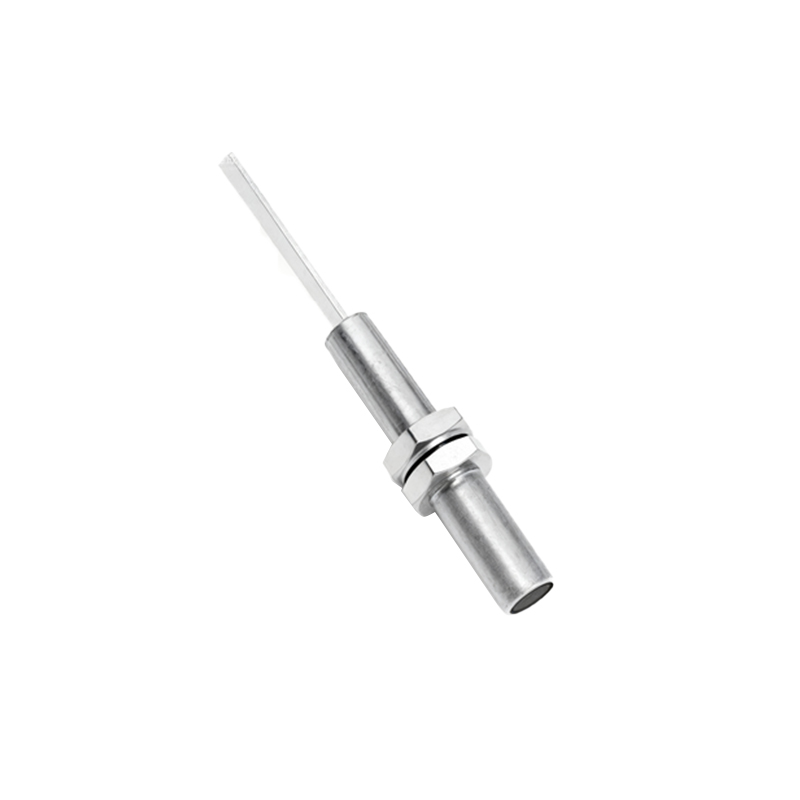
NPN (Sinking) Sensors: Conversely, an NPN sensor's output switch is connected to the negative voltage supply. When active, it "sinks" current to ground, effectively completing the circuit by connecting the load to 0V. Here, the load must be connected between the positive supply and the sensor's output wire. A typical three-wire NPN sensor also has brown (24V+), blue (0V), and black (output) wires. However, in this case, the black wire switches to 0V upon detection. NPN wiring is commonly used in North America and Japan.
Namur Sensors: These are two-wire, intrinsically safe sensors designed for hazardous environments. They do not switch the full load current directly. Instead, they produce a small current signal change (e.g., from 1 mA to 3 mA) which must be interpreted by a separate isolating amplifier or safety barrier. The amplifier then provides the robust switching signal to the control system. Wiring is simpler (just two wires in series with the power supply and amplifier), but the associated control electronics are mandatory.
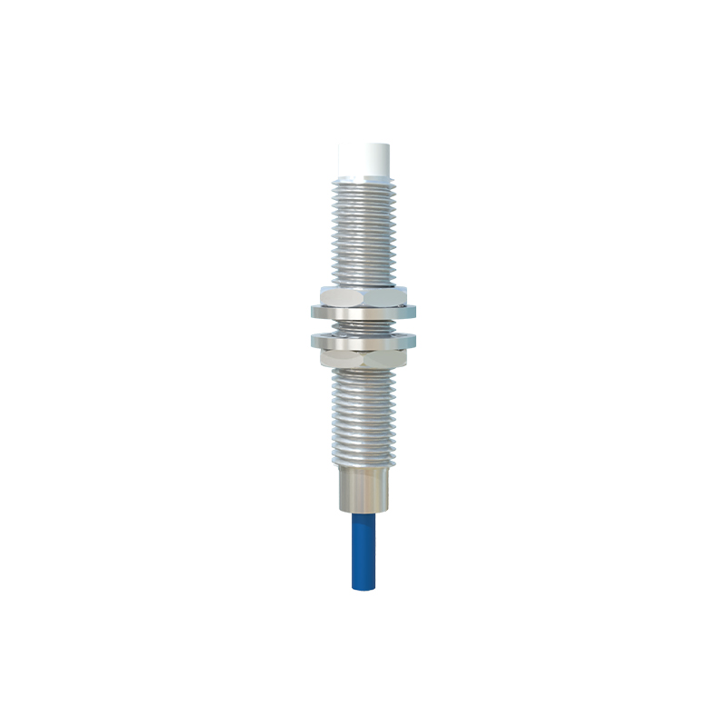
Beyond the output type, wiring practices are critical. Always refer to the manufacturer's datasheet for the specific pinout and voltage ratings. Key steps include:
1. Power Supply: Use a stable, regulated DC power supply, typically 10-30V DC, matching the sensor's specification. Ensure correct polarity; reversing power on a three-wire sensor can cause permanent damage.
2. Shielding: In environments with significant electromagnetic interference (EMI) from motors or frequency drives, use shielded cables. Connect the cable shield to a functional earth ground at the control cabinet end only, avoiding ground loops.
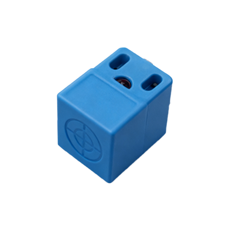
3. Load Connection: Connect the load (PLC input, relay coil, indicator lamp) correctly in series based on whether the sensor is PNP or NPN. Ensure the load's current and voltage ratings are within the sensor's switching capacity. A flyback diode is recommended for inductive loads like relay coils to suppress voltage spikes that can damage the sensor's output transistor.
4. Wiring Protection: Route sensor cables away from high-power lines. Use conduit in harsh environments to protect against physical damage, oils, and coolants. Implement proper strain relief at connections.
5. Diagnostics: Many modern sensors feature LED indicators. A steadily lit LED when a target is present confirms basic operation. Flashing patterns often indicate issues like short circuits, overloads, or sensor malfunction, aiding in rapid troubleshooting.
A common wiring fault involves mixing PNP and NPN sensors with an incompatible PLC input module. Most sinking (NPN) input modules require a sourcing (PNP) sensor, and most sourcing input modules require a sinking sensor. Understanding this complementary relationship prevents frustrating commissioning delays. For complex multi-sensor installations, careful planning of the wiring harness, labeling, and documentation is essential for future maintenance.
In summary, proper proximity sensor wiring is a systematic discipline. Selecting the correct output type (PNP/NPN/Namur) for the control system, adhering to robust installation practices, and implementing basic protective measures are the foundations of a fail-safe detection system. A well-wired sensor network minimizes downtime, enhances safety, and ensures the seamless flow of automated processes, proving that in industrial automation, success is often determined by the quality of the connections.