Proximity sensors are fascinating devices that detect the presence or absence of an object within a certain range without any physical contact. This hands-on experiment guide is designed to help students, hobbyists, and engineers understand the fundamental principles and practical applications of these ubiquitous sensors. By building a simple circuit and observing its behavior, one can gain deep insights into the world of non-contact detection.
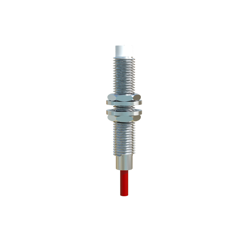
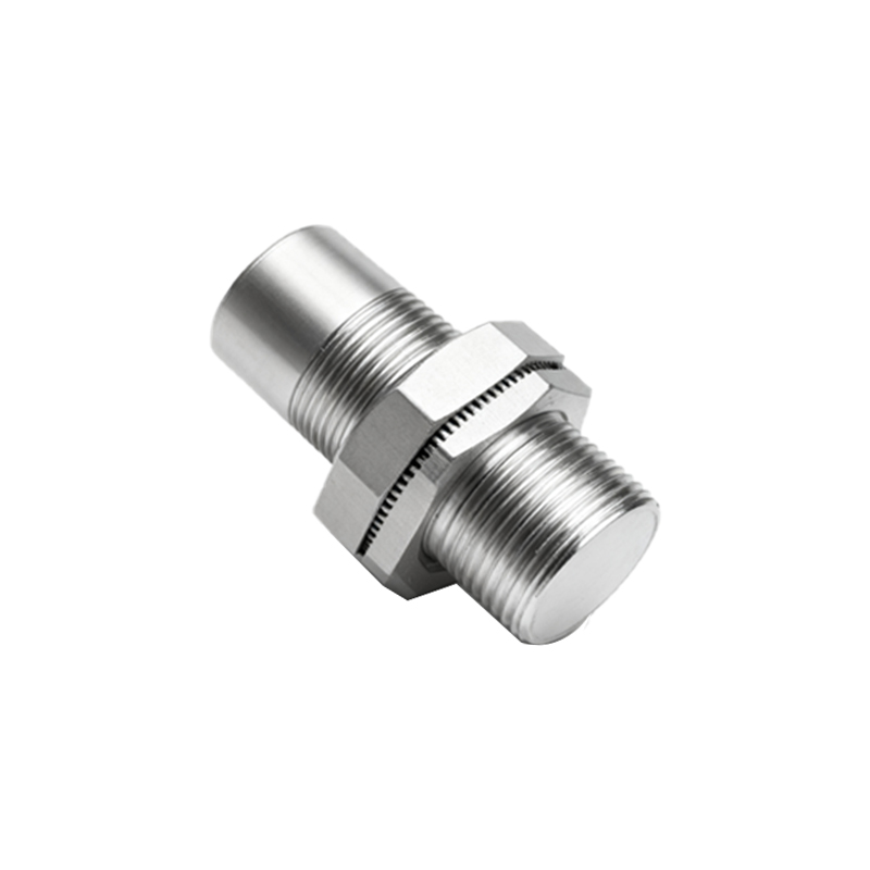
The core principle behind most proximity sensors involves emitting a field or beam and monitoring for changes in that field. Common types include inductive sensors for detecting metallic objects, capacitive sensors for both metallic and non-metallic materials, and photoelectric sensors that use light beams. For this basic experiment, we will focus on constructing a simple infrared (IR) proximity sensor, as its components are readily available and its operation is visually intuitive.
To begin the experiment, gather the necessary components. You will need an IR LED, an IR photodiode or phototransistor, a standard LED (for visual output), a 220-ohm resistor, a 10k-ohm resistor, an operational amplifier (like the LM358), a breadboard, and jumper wires. A power source, such as a 5V battery pack or USB power supply, is also required. The IR LED will act as the transmitter, constantly emitting infrared light. The IR photodiode is the receiver, positioned next to the transmitter. When an object comes close, the infrared light reflects off the object and strikes the photodiode.
Start by constructing the transmitter circuit. Connect the anode of the IR LED to the positive power rail through the 220-ohm current-limiting resistor. Connect its cathode to the ground rail. This circuit will cause the IR LED to emit light continuously. Next, build the receiver circuit. Connect the cathode of the IR photodiode to the positive rail. Connect its anode to one end of the 10k-ohm resistor, and connect the other end of this resistor to ground. This point, the anode of the photodiode, is your signal node. The voltage here will change based on the amount of IR light received.
This signal is very weak, so we need an amplifier. Configure the operational amplifier as a comparator. Connect the non-inverting input (+) of the op-amp to the signal node from the photodiode. Use a voltage divider (two resistors) to create a reference voltage of approximately 2.5V and connect it to the inverting input (-). The output of the op-amp will then connect to the anode of the standard LED (with a 220-ohm resistor in series), whose cathode goes to ground. When the signal voltage exceeds the reference voltage, the op-amp's output goes high, lighting the visible LED.
Now, power the circuit. Point the IR LED and photodiode towards an open space. The visible LED should remain off. Slowly bring your hand or a piece of white paper closer to the sensor pair. Observe the moment the visible LED turns on, indicating detection. Experiment with different materials, colors, and distances. You will notice that reflective surfaces like white paper are detected from a farther distance than dark, non-reflective surfaces. Try to measure the maximum detection range.
This simple experiment demonstrates key concepts: the use of reflected infrared light for detection, the need for signal conditioning (amplification and comparison), and the impact of object properties on sensor performance. The threshold detection distance can be adjusted by changing the reference voltage on the comparator's inverting input. A lower reference voltage makes the sensor more sensitive.
Beyond this basic setup, consider exploring variations. Replace the comparator circuit with a microcontroller like an Arduino. This allows you to read analog values from the photodiode, map detection distances, and create more complex output logic. You can also experiment with different sensor orientations. A common configuration is to mount the IR LED and receiver side-by-side; this is called diffuse or reflective sensing. For more precise short-range detection, sensors are often mounted facing the same direction, relying on the object to reflect light back—a principle used in many commercial devices.
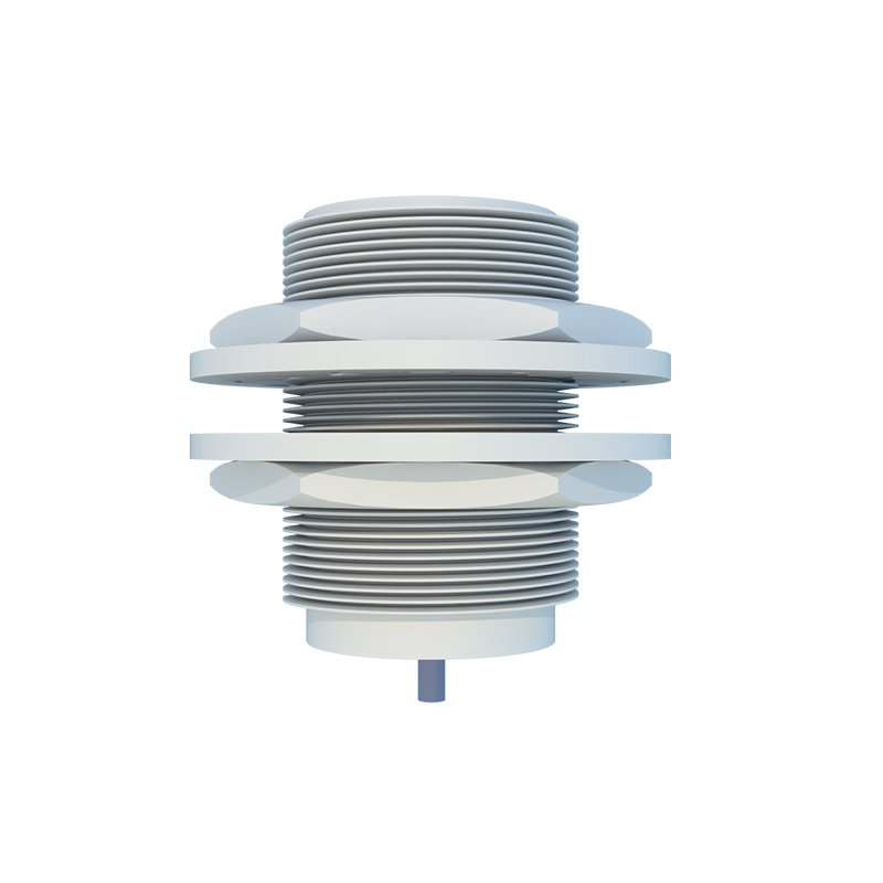
Understanding this fundamental operation is crucial for real-world applications. Proximity sensors are integral to smartphones (turning off the screen during a call), industrial automation (counting objects on a conveyor belt), robotics (obstacle avoidance), and automotive systems (parking assistance). Each application may use a different underlying technology—inductive, capacitive, ultrasonic, or optical—but the core logic of non-contact presence detection remains consistent.
This experiment provides a tangible foundation. By physically connecting components and observing the cause-and-effect relationship between object distance and circuit output, the abstract data sheet specifications become concrete knowledge. Troubleshooting issues, such as insufficient sensitivity or interference from ambient light, further develops practical engineering skills. Always document your observations, measure voltages at different test points, and sketch circuit diagrams. This