Wiring a laser infrared sensor correctly is crucial for ensuring accurate detection, reliable operation, and long-term system stability. These sensors, widely used in automation, security, and industrial applications, convert infrared light signals into electrical outputs. While specific models may have unique requirements, the fundamental wiring principles remain consistent. This guide provides a step-by-step overview of the standard wiring process, essential precautions, and common troubleshooting tips.
First, identify the sensor's terminals. A typical laser infrared sensor has at least three wires: power supply, ground, and output. The power wire (often labeled Vcc, +V, or 12-24VDC) connects to the positive terminal of your DC power source. The ground wire (labeled GND, COM, or 0V) connects to the negative terminal. The output wire (often labeled OUT, NO/NC, or signal) carries the detection signal to your controller, such as a PLC, relay, or microcontroller. Some advanced sensors may have additional wires for analog output, timing functions, or communication protocols like IO-Link.
Before connecting any wires, always disconnect power to the circuit. Verify the power supply voltage matches the sensor's specifications, usually printed on its housing. Common ratings are 12-24V DC. Using an incorrect voltage can permanently damage the sensor. Use stranded copper wire of appropriate gauge, typically 18-22 AWG, for flexible and secure connections. For long cable runs or electrically noisy environments, consider using shielded cable and grounding the shield at one end to prevent interference.
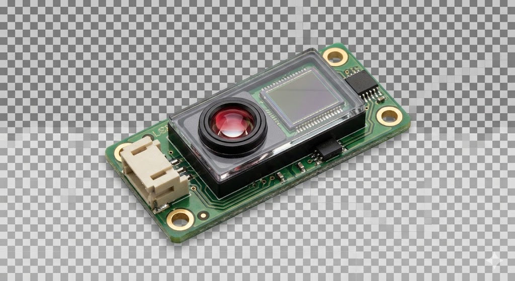
Strip about 7mm of insulation from each wire end. If using a connector, crimp or solder the wires securely. For screw terminals, ensure the wire is firmly clamped without stray strands that could cause short circuits. Connect the power and ground wires first. Apply power momentarily and check for a power indicator LED, if present. This confirms basic electrical connectivity.
Next, connect the output wire. The output type is critical. A digital PNP (sourcing) output provides a positive voltage when active, while an NPN (sinking) output connects the load to ground. Ensure your controller's input type is compatible. For a simple relay interface, connect the sensor output to the relay coil terminal. For a PLC, connect to the designated digital input. Always install a protective device like a fuse or circuit breaker in the power line.
After wiring, perform functional testing. Power the system and observe the sensor's behavior. Many sensors have a stability or power-on LED. Point the sensor at a target within its specified range. The output LED should activate upon detection. Use a multimeter to verify the output voltage switches correctly between its on and off states. Check for false triggers by moving objects outside the detection zone.
Common wiring issues include reversed polarity, loose connections, and electrical noise. Reversed polarity often blows an internal fuse or damages circuitry. Loose connections cause intermittent operation. In industrial settings, noise from motors or welders can disrupt sensor signals. Ensure proper grounding, use twisted-pair or shielded cables, and keep sensor cables away from high-voltage lines. If the sensor behaves erratically, temporarily power it from a separate, clean supply to isolate the issue.
Environmental factors also affect performance. Ensure the sensor lens is clean and free of obstructions. Avoid mounting near reflective surfaces or direct sunlight, which can interfere with infrared light. Adhere to the specified sensing distance and alignment requirements. For long-range applications, secure mounting is essential to prevent vibration from misaligning the laser beam.
Regular maintenance involves periodic inspection of cables and connections for wear or corrosion. Check the mounting hardware for tightness. Clean the lens with a soft, dry cloth. Log any operational anomalies for preventive analysis.
In summary, proper wiring of a laser infrared sensor involves careful planning, adherence to electrical specifications, and methodical testing. By following these guidelines, you can ensure robust integration into your control system, minimizing downtime and maximizing sensor lifespan. Always consult the manufacturer's datasheet for model-specific details, as wiring colors, terminal functions, and special features can vary.