Building your own proximity sensor can be a rewarding and educational electronics project. It allows you to understand the fundamental principles of sensing technology while creating a functional device for various applications. This guide will walk you through creating a basic infrared (IR) proximity sensor, a common and versatile type. Remember, working with electronics requires basic safety precautions. Always disconnect power when making connections, and be mindful of static electricity around sensitive components.
To begin, you will need to gather the necessary components. The core of this project involves an IR transmitter (an IR LED) and an IR receiver (a phototransistor or photodiode). You will also require a resistor for the LED (typically 220-330 ohms), a resistor for the receiver (around 10k ohms), a general-purpose NPN transistor (like BC547 or 2N2222), a standard LED for visual output, a breadboard for prototyping, jumper wires, and a power source such as a 5V DC supply or a 9V battery with a regulator. Optionally, you can include a buzzer for an audible alert.
The operating principle is straightforward. The IR LED constantly emits infrared light, which is invisible to the human eye. When an object comes close, the infrared light reflects off the object and is detected by the IR receiver. The receiver's conductivity changes based on the amount of IR light it receives. This change is then amplified and processed by the circuit to trigger an output.
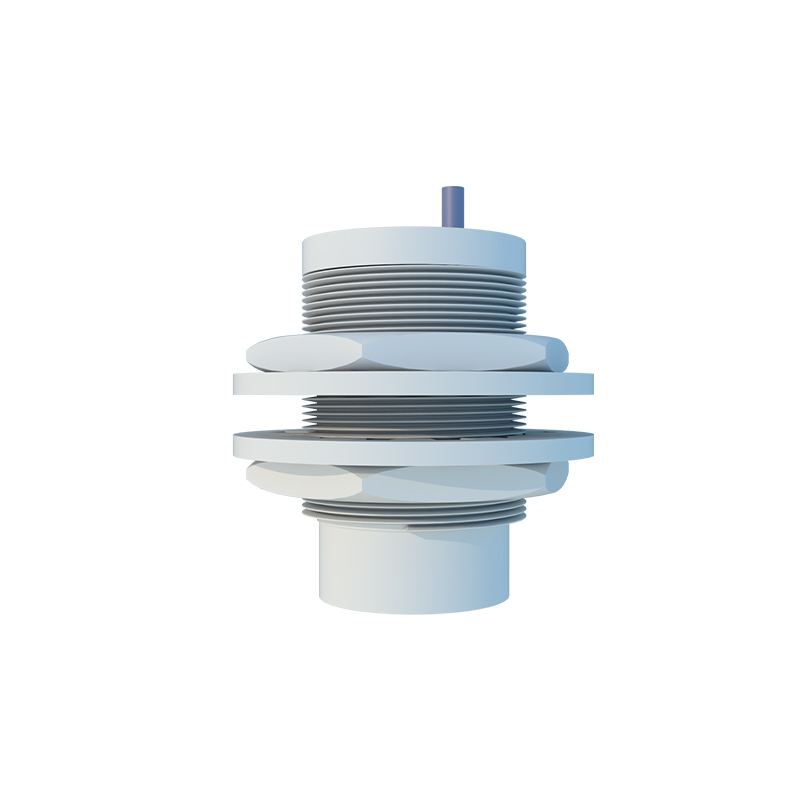
Let's construct the circuit step-by-step. First, place all components on the breadboard. Connect the positive rail of the breadboard to your power supply's positive terminal (5V is ideal) and the negative rail to ground. For the transmitter side: connect the anode (longer leg) of the IR LED to the positive rail through a 220-ohm current-limiting resistor. Connect the cathode (shorter leg) directly to the ground rail. This IR LED will now be constantly on.
Now, for the receiver circuit. Connect the collector pin of the phototransistor (if using a three-legged type, refer to its datasheet) to the positive rail through a 10k ohm pull-up resistor. Connect the emitter pin directly to ground. The point between the phototransistor's collector and the 10k resistor is your signal output. This point will have a voltage that drops when IR light is detected.
Next, we need to amplify this signal to drive an output indicator. Connect the base of your NPN transistor (e.g., BC547) to the signal output point (the junction of the phototransistor's collector and the 10k resistor) through a 1k ohm resistor. Connect the emitter of the NPN transistor to ground. Connect the collector of the NPN transistor to the cathode (shorter leg) of a standard visible LED. Then, connect the anode of this visible LED back to the positive rail through another 220-ohm resistor.
Here’s how it works in action. With no object nearby, the IR receiver detects minimal reflected light. The signal point voltage remains high, keeping the NPN transistor off, so the visible LED is off. When an object approaches, reflected IR light hits the receiver, causing its conductivity to increase. This pulls the signal point voltage lower, which turns on the NPN transistor. This completes the circuit for the visible LED, causing it to light up, indicating detection.
After assembling the circuit on the breadboard, apply power. Test the sensor by moving your hand or a white object in front of the IR pair. The visible LED should illuminate when an object is close. If it doesn't work, double-check all connections. Ensure the IR LED is emitting by pointing a smartphone camera at it; most camera sensors can see the IR light as a faint purple glow. Adjust the positioning of the IR transmitter and receiver. They should be placed side-by-side, angled slightly towards a common focal point a few centimeters away. You may need to experiment with the resistor values for the receiver (the 10k resistor) to adjust sensitivity. A higher value resistor makes it more sensitive.
For more stable performance, you can integrate an operational amplifier (op-amp) like the LM358 in a comparator configuration. This allows you to set a precise detection threshold using a voltage divider and provides a cleaner digital output. You can also replace the visible LED with a relay module to control AC appliances, but exercise extreme caution with high voltage.
This homemade sensor is perfect for non-critical applications like a touchless switch, a simple object counter, or an automatic tap prototype. Its range is limited, typically a few centimeters, and it can be affected by ambient IR light (sunlight, incandescent bulbs). Using modulated IR signals (switching the IR LED on/off rapidly) and a tuned receiver can greatly improve immunity