Proximity sensors are indispensable components in modern automation, manufacturing, and consumer electronics. Their primary function is to detect the presence or absence of an object within a specified range without physical contact. However, the efficacy of these sensors hinges on precise adjustment and calibration. Incorrect settings can lead to false triggers, missed detections, and system failures. This guide provides a comprehensive overview of the principles and practical steps for adjusting proximity sensors to ensure reliable operation.
Understanding the core types is the first step. Inductive sensors detect metallic objects, while capacitive sensors can detect both metallic and non-metallic materials, including liquids and powders. Ultrasonic sensors use sound waves, and photoelectric sensors rely on light beams. Each type has distinct adjustment parameters and considerations. Before any adjustment, consult the manufacturer's datasheet for specific specifications regarding sensing distance, hysteresis, and environmental limits.
The adjustment process typically involves several key parameters. The sensing distance, often labeled as the nominal range (Sn), is the maximum distance at which the sensor can reliably detect a standard target. It is crucial to note that the effective sensing distance can be affected by the target material, size, and shape. For instance, an inductive sensor's range reduces for non-ferrous metals compared to steel. Always perform adjustments using the actual target material under real operating conditions.
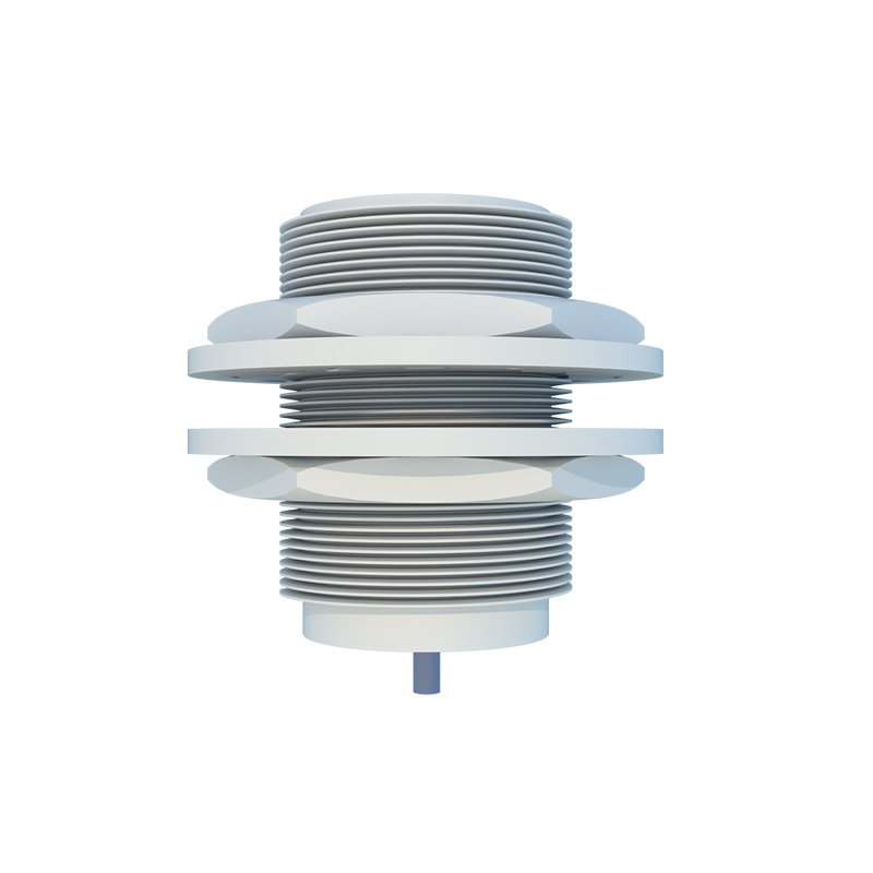
Hysteresis is a critical feature that prevents output oscillation when a target is at the edge of the detection zone. It is the difference between the switch-on point (when the target approaches) and the switch-off point (when the target moves away). A properly set hysteresis ensures a stable output signal. Most sensors have a fixed hysteresis percentage (e.g., 3-10% of Sn), but some advanced models allow for manual adjustment to suit specific application needs, such as controlling vibration or dealing with slowly moving objects.
The response time, or switching frequency, defines how quickly the sensor can react to a changing target presence. Adjusting this parameter is essential for high-speed applications. Setting a response time that is too slow may cause the system to miss objects on a fast-moving conveyor. Conversely, an excessively fast response time in a noisy electrical environment might make the sensor susceptible to interference. Finding the optimal balance is key.
Output configuration adjustment is another vital step. Sensors may provide digital (ON/OFF), analog (current or voltage proportional to distance), or IO-Link outputs. For digital types, ensure the output logic (NPN sinking or PNP sourcing) matches the controller's input requirements. For analog sensors, the scaling (e.g., 4-20mA for 0-10mm) must be correctly calibrated to translate the signal into accurate positional data in the control system.
Environmental factors significantly impact performance. Temperature fluctuations can cause sensing range drift. Adjustments made in a controlled lab environment may not hold on a factory floor. Electrical noise from motors or variable frequency drives can induce false signals. Proper shielding, grounding, and, where adjustable, increasing the sensor's noise immunity setting are necessary steps. For sensors in washdown areas, verify the housing integrity and adjust sensitivity if condensation or debris accumulation is a concern.
A systematic approach to field adjustment is recommended. First, install the sensor securely, aligning it correctly with the target's path. Power the system and introduce the standard target. Use a non-metallic tool if adjusting potentiometers to avoid interference. For sensors with teach-in functions (often a button or a magnetic actuator), follow the procedure: present the target at the desired "detect" point and activate the teach-in, then remove the target to the desired "release" point and activate again. This programs the on and off thresholds automatically.
Fine-tuning often requires an iterative process. Observe the sensor's LED indicator (if available) and monitor the output on the controller. Test with multiple targets and under varying speeds. It is advisable to create a margin of safety; set the detection point slightly closer than the maximum possible range to account for mechanical wear, target tolerances, and environmental drift. Document the final settings for future maintenance and troubleshooting.
Regular verification and recalibration form part of a robust maintenance schedule. Over time, mechanical shock, lens contamination (for optical types), or component aging can degrade performance. Establish a periodic check using a calibrated gauge to ensure the sensing distance remains within acceptable limits. This proactive approach minimizes unplanned downtime.
In summary, effective proximity sensor adjustment is not a one-time setup but a disciplined application of technical knowledge. By understanding sensor types, meticulously configuring key parameters like sensing distance, hysteresis, and response time, and accounting for real-world environmental factors, technicians can optimize sensor performance. This ensures enhanced system reliability, improved product quality, and sustained operational efficiency across diverse industrial and technological applications.