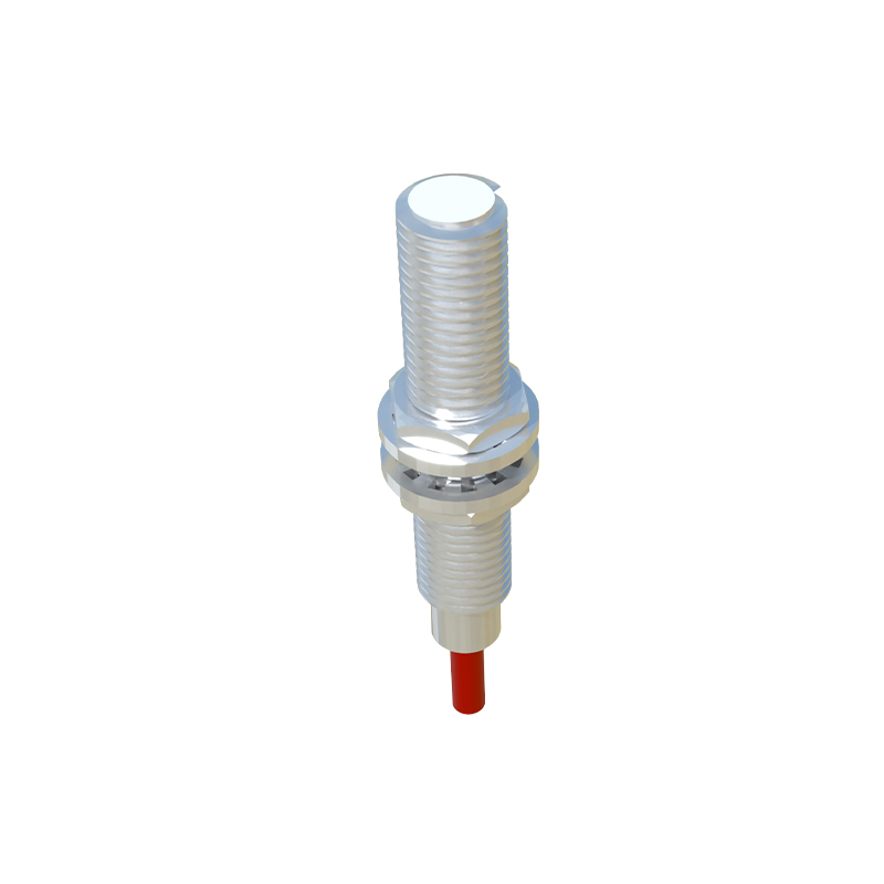
Building your own proximity sensor is a rewarding electronics project that combines fundamental principles with practical application. This guide will walk you through creating a basic infrared (IR) proximity sensor, a common and versatile type used for object detection. The process demystifies the technology behind automatic faucets, robotics, and many industrial systems.
The core principle of an IR proximity sensor involves emitting an infrared light beam and detecting its reflection. An object within a specific range will reflect the light back to a receiver. The sensor then interprets this signal. For this project, you will need an IR LED (Light Emitting Diode), a photodiode or phototransistor (as the IR receiver), a 100-ohm resistor, a 10k-ohm resistor, an LM358 operational amplifier (op-amp) IC, a breadboard, jumper wires, and a 5V power source, such as a USB cable or battery pack.
Begin by placing the LM358 op-amp on the breadboard, straddling the center gap. Connect Pin 8 (VCC) to the positive rail and Pin 4 (GND) to the negative rail. This provides power. The first stage is the transmitter circuit. Take the IR LED. Its longer lead (anode) is positive. Connect this anode to the positive rail through the 100-ohm current-limiting resistor. Connect the shorter cathode lead directly to the negative rail. This circuit will constantly emit infrared light, invisible to the human eye.
Next, construct the receiver and amplifier circuit. This is crucial for detecting the weak reflected signal. Insert the photodiode. Ensure you identify the cathode (often marked by a longer lead or a flat edge on the casing). Connect the photodiode's cathode to the positive rail. Connect its anode to one end of the 10k-ohm resistor. Link the other end of this resistor to the negative rail. This point, where the photodiode's anode and the 10k-ohm resistor meet, is your signal node. This node connects to Pin 3 (the non-inverting input) of the first op-amp on the LM358 (Pins 1, 2, 3).
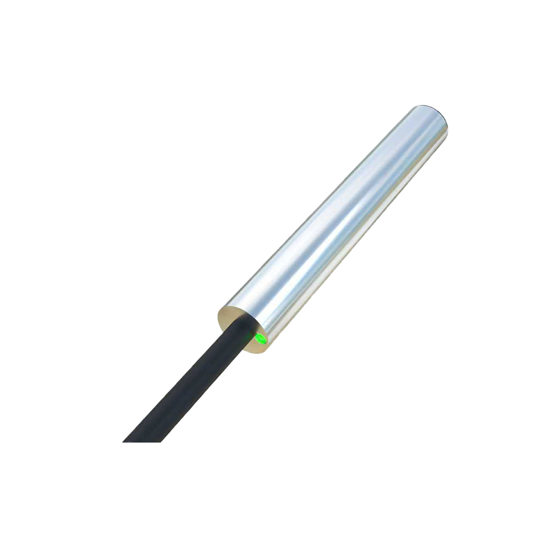
Now, set up the op-amp as a comparator. Connect a wire from Pin 2 (the inverting input) to a new point on the breadboard. This will be your reference voltage, created using a voltage divider. To make a simple divider, connect two 10k-ohm resistors in series between the positive and negative rails. The junction between these two resistors provides a reference voltage of approximately 2.5V. Connect this junction to Pin 2. Finally, connect Pin 1 (the output of this first op-amp) to a simple output indicator, like an LED in series with a 220-ohm resistor to the negative rail.
The system operates on a comparison. When no object is near, the photodiode receives little to no reflected IR light. The voltage at Pin 3 is low (below 2.5V). The op-amp compares this to the 2.5V at Pin 2, and its output (Pin 1) goes low, keeping the indicator LED off. When an object comes close, it reflects the IR beam onto the photodiode. This increases the photodiode's conductivity, raising the voltage at Pin 3 above 2.5V. The op-amp's output immediately switches high, lighting the indicator LED. The detection range can be adjusted by changing the value of the resistor in the voltage divider connected to Pin 2 or by using a potentiometer for fine-tuning.
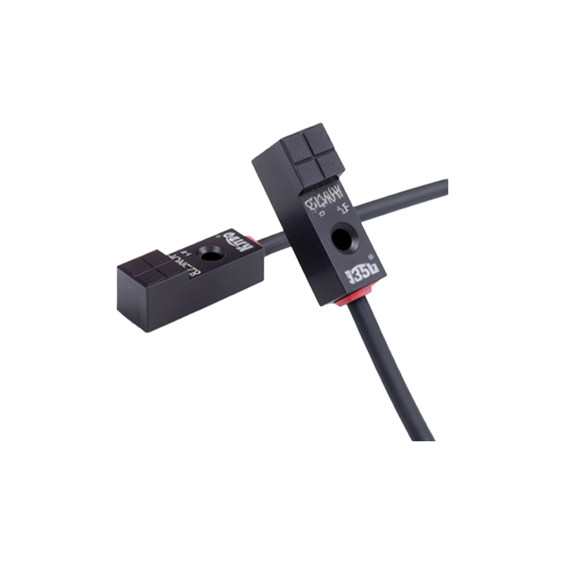
Testing is straightforward. Power the circuit and observe the indicator LED. It should remain off. Slowly bring a non-shiny, light-colored object (like a piece of white paper) toward the IR LED and photodiode, keeping them side-by-side. At a distance of roughly 5-15 cm, the indicator LED should illuminate. Move the object away, and it should turn off. Dark or highly absorbent materials may not reflect well, and bright ambient light can interfere. For better performance, you can house the IR LED and photodiode in a small tube to shield them from side light and direct them forward.
This basic sensor can be the foundation for numerous applications. By replacing the indicator LED with a relay module, you can control AC appliances. Integrating the output into an Arduino or Raspberry Pi allows for distance logging, robotics navigation, or touchless interfaces. The act of building it reinforces understanding of key concepts: infrared light, photoelectric effect, signal amplification, and voltage comparison. With this hands-on knowledge, you can modify designs, experiment with different sensor types like ultrasonic modules, and develop more complex automated systems.