Proximity sensors are indispensable components in modern industrial automation, robotics, and countless electronic devices. Their ability to detect the presence or absence of an object without physical contact ensures reliability, longevity, and efficiency. However, simply installing a sensor is rarely enough. Proper adjustment, or tuning, is critical to achieving the specified sensing range, accuracy, and stability required for a specific application. This guide outlines the fundamental principles and practical steps for correctly adjusting proximity sensors.
Understanding the core types is the first step. Inductive proximity sensors detect metallic objects. Capacitive sensors can detect both metallic and non-metallic materials, including liquids and powders. Ultrasonic sensors use sound waves to measure distance to objects of various materials, while photoelectric sensors utilize a light beam. Each type has distinct adjustment parameters and considerations.
Before any adjustment, prioritize safety. Ensure the system is in a safe state, typically with power locked out and tagged out (LOTO), especially in industrial settings. Never attempt adjustments on a live, moving machine unless explicitly trained and following safe procedures. Gather the necessary tools: the sensor's datasheet, a suitable target object (identical to the one it will sense in operation), and any adjustment tools like a small screwdriver or, for modern sensors, a programming interface or HMI.
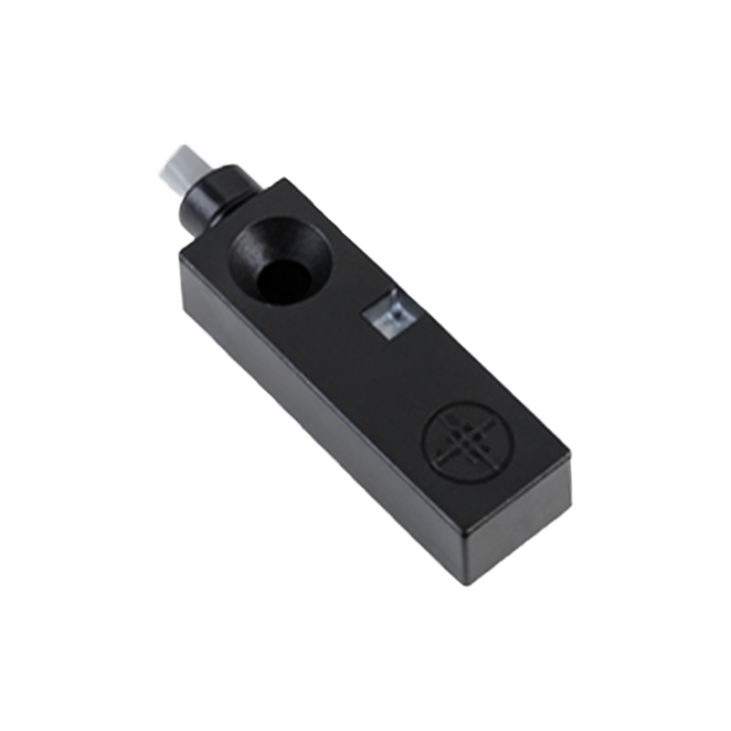
The primary adjustment for most proximity sensors involves setting the sensing distance or threshold. Many sensors feature a potentiometer (a small adjustable resistor) or DIP switches for this purpose. The goal is to set the detection point reliably within the sensor's nominal range, accounting for real-world variables.
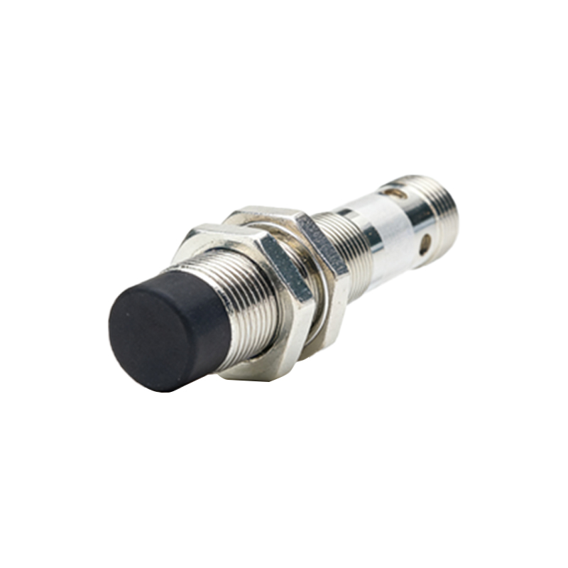
Step-by-Step Adjustment Process:
1. Initial Installation & Positioning: Mount the sensor securely according to the datasheet specifications. Pay attention to mounting flushness, material surroundings (metal can affect inductive sensors), and the recommended gap between the sensor face and the target. Position the correct target object at the desired detection point.
2. Power On & Observe Default State: Apply power. Most sensors have an LED indicator that shows power (usually green) and output state (usually yellow or orange when an object is detected). Note the initial behavior.
3. Fine-Tuning the Sensitivity/Distance: Using the adjustment tool, slowly turn the potentiometer or change the switch settings. Have the target object repeatedly move into and out of the sensing field. The key is to find the "threshold" point. Turn the adjuster until the output LED just activates when the target is in the desired position. Then, continue slightly past this point to provide a safety margin, or "hysteresis." This margin prevents erratic toggling of the output if the target vibrates or stops precisely at the edge of the sensing range. For sensors with teach-in functions (common in ultrasonic and advanced models), follow the manufacturer's procedure, which often involves pressing a button when the target is at the desired near and far points.
4. Testing Under Real Conditions: This is the most crucial phase. Test the sensor not just with a perfect, static target, but under actual operating conditions. Cycle the machine or process. Use the actual targets that may vary slightly in size, material, or position. Check for false triggers caused by environmental factors: for inductive sensors, watch for different metals; for capacitive, watch for humidity or material density changes; for photoelectric, watch for ambient light or dust; for ultrasonic, watch for temperature fluctuations or soft materials that absorb sound.
5. Document Settings: Once optimal performance is achieved, document the potentiometer position or switch settings. For sensors with multiple adjustments (like response time or output mode), ensure these are also correctly configured for the application—fast response for high-speed counting or a delay-off function for conveyor jams.
Common Adjustment Challenges and Solutions:
Sensor Triggers Erratically: This is often due to insufficient hysteresis or an environmental interference. Increase the hysteresis margin, shield the sensor from electrical noise, or adjust the sensitivity downward slightly. Ensure the sensor is not detecting a background object.
Sensor Does Not Trigger at Required Distance: The target may be outside the sensor's effective range for its size and material. Consult the datasheet for reduction factors (for inductive sensors sensing non-ferrous metals, for instance). You may need a sensor with a longer range. Also, check for sensor overload or incorrect wiring.
Inconsistent Performance with Different Targets: Standardize the target material and size if possible. If not, adjust the sensor to the "worst-case" target (e.g., the smallest or least detectable) and verify it works for all others. A sensor with a wider operating margin may be required.
Regular verification of sensor adjustment is part of preventive maintenance. Vibration can cause potentiometers to drift, and environmental buildup on the sensor face can diminish performance. A scheduled check ensures continued system reliability.
In summary, effective