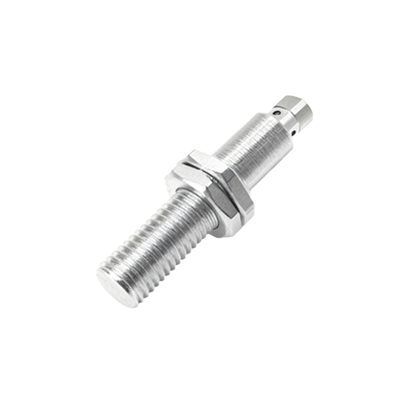
In industrial automation and consumer electronics, proximity sensors play a crucial role in detecting the presence or absence of objects without physical contact. Understanding how to program these devices effectively requires a clear grasp of their operational diagrams. This guide delves into the core components of proximity sensor programming diagrams, offering practical insights for engineers and developers.
A proximity sensor programming diagram typically illustrates the logical flow and electrical connections necessary for sensor integration. At its heart, the diagram includes the sensor module, microcontroller or PLC (Programmable Logic Controller), power supply, and output actuators. The sensor module itself consists of an oscillator, detection coil, and signal conditioning circuit. When an object enters the sensor's electromagnetic field, it alters the oscillation, triggering a detection signal. This signal is then processed by the microcontroller based on predefined logic.
The programming aspect revolves around configuring the microcontroller to interpret sensor inputs accurately. For instance, in a basic setup, the diagram might show a digital output pin connected to an LED or relay. The code snippet—often represented in ladder logic for PLCs or C/C++ for embedded systems—defines conditions such as "IF sensor detects object, THEN activate output." Timing parameters, like response delay or hysteresis, are also specified to prevent false triggers. Advanced diagrams incorporate multiple sensors in networked systems, using protocols like I2C or Modbus for communication.
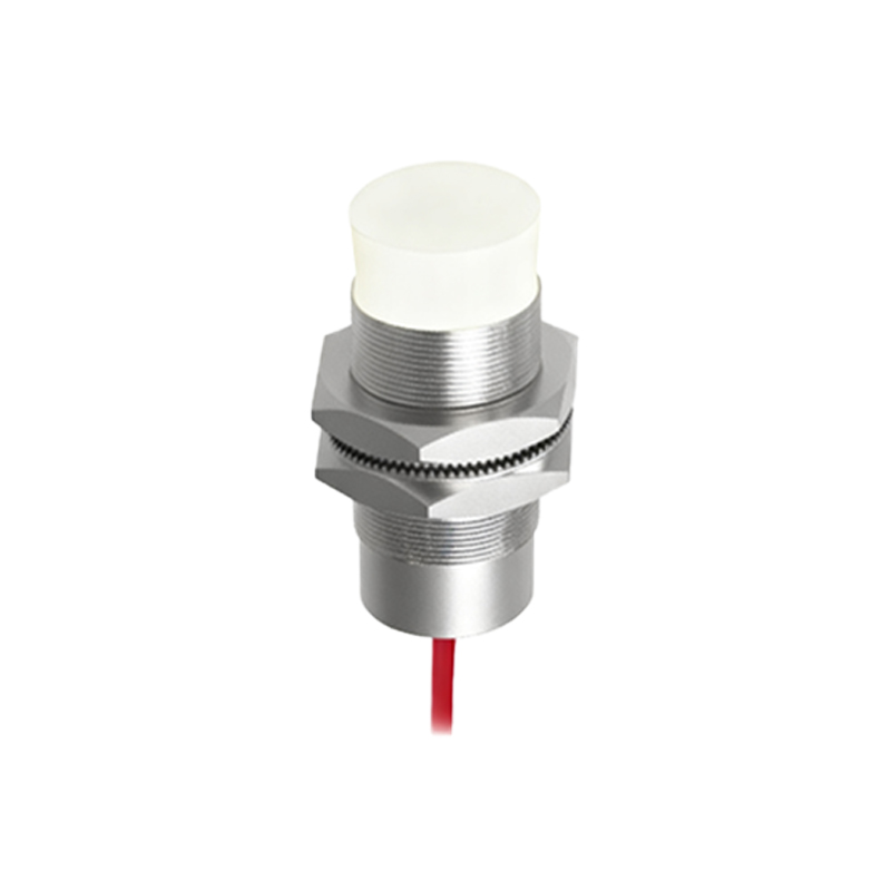
Key considerations when reading these diagrams include voltage levels (e.g., 5V DC for electronics, 24V DC for industrial use), wiring schematics (sourcing vs. sinking configurations), and environmental factors like interference shielding. For example, inductive proximity sensors, common in metal detection, require diagrams that account for sensing range adjustments, while capacitive types for non-metallic objects may include sensitivity calibration circuits.
Implementing a proximity sensor program involves testing and optimization. Engineers use simulation tools to validate diagrams before deployment, ensuring reliability in applications like robotic arms, conveyor systems, or touchless interfaces. Troubleshooting tips, such as checking ground loops or signal noise, are often annotated in detailed diagrams.
Ultimately, a well-designed programming diagram serves as a blueprint for efficient sensor operation. It bridges hardware and software, enabling seamless automation. As technology evolves, integrating IoT capabilities—where sensors send data to cloud platforms—adds layers to these diagrams, emphasizing scalability and real-time monitoring. By mastering proximity sensor diagrams, professionals can enhance system precision and adaptability across diverse industries.