In the world of industrial automation, electronics, and circuit design, symbols serve as a universal language. Among these, the proximity sensor symbol is a critical component in schematic diagrams, providing a clear and standardized way to represent non-contact detection devices. Understanding this symbol is essential for engineers, technicians, and anyone involved in reading or creating electrical blueprints.
A proximity sensor, by definition, is a device that can detect the presence or absence of a nearby object without any physical contact. It does this by emitting an electromagnetic field or a beam of radiation (like infrared light) and then looking for changes in the field or return signal. The symbol for such a sensor must, therefore, convey this concept of non-contact sensing visually and intuitively.
The standard electrical symbol for a proximity sensor, as defined in international standards like IEC 60617, often resembles a standard sensor or switch symbol but is modified with specific graphical elements to indicate its function. A common representation features a diamond shape, which is the fundamental symbol for a sensor in many diagramming standards. Inside or adjacent to this diamond, two parallel lines or arcs are drawn, typically radiating outward. These lines symbolize the emitted field or beam. Sometimes, the symbol may include an arrow pointing away from the diamond, further emphasizing the emission and detection direction. The symbol is usually labeled with the letters "PRX" or "PROX" for clarity. It is important to note that the exact depiction can vary slightly depending on the drafting standard (IEC, ANSI, JIC) or the specific type of proximity sensor—inductive, capacitive, or photoelectric.
The primary purpose of using this standardized symbol is to ensure unambiguous communication across different teams, companies, and countries. On a complex schematic for a manufacturing assembly line or a vehicle's control system, seeing the proximity sensor symbol immediately informs the reader that a component in that location detects objects via a field. This allows for quick analysis of the circuit's logic: Is it detecting a metal part on a conveyor? Is it ensuring a safety door is closed? The symbol, combined with its label and connection points, answers these questions at a glance.
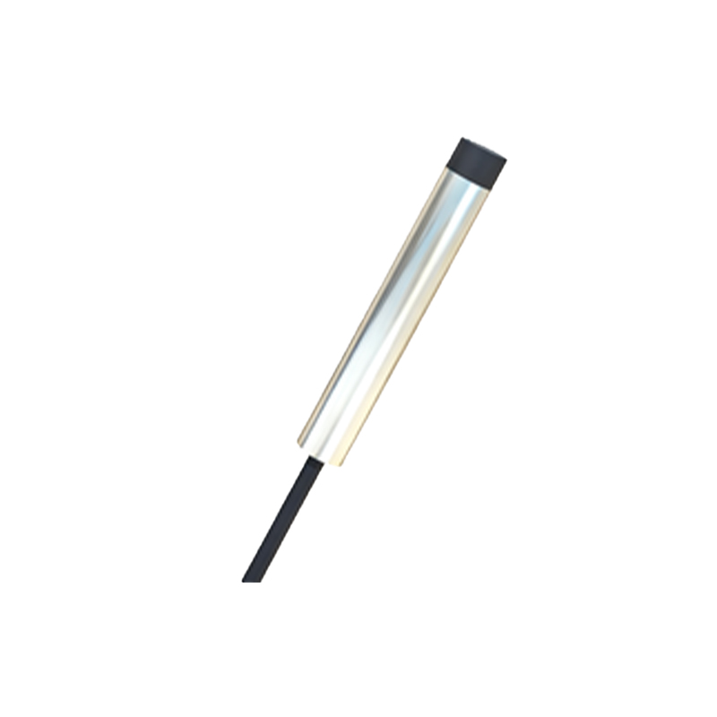
Let's consider its application in a typical ladder logic diagram for an industrial machine. A proximity sensor symbol would be placed in the input section of the rung. Its normally open or normally closed contact configuration (often indicated by the shape of the switch inside the diamond) shows how it interacts with the control logic. When the sensor detects an object, its state changes, completing or breaking the circuit to activate a solenoid, motor starter, or PLC input. This visual representation is far more efficient than lengthy textual descriptions.
Beyond standard electrical schematics, the proximity sensor icon or a simplified version of its symbol is frequently used in human-machine interface (HMI) screens, technical manuals, and equipment labeling. In these contexts, it helps operators identify the physical location and function of the sensor on the actual machine. Recognizing the symbol fosters safer and more efficient troubleshooting and operation.
For students and new professionals entering fields like mechatronics, robotics, or industrial maintenance, learning to identify and interpret the proximity sensor symbol is a foundational skill. It bridges the gap between theoretical knowledge of sensor operation and the practical ability to navigate real-world technical documentation. Misinterpreting this symbol could lead to wiring errors, faulty system logic, or even safety hazards.
In summary, the proximity sensor symbol is more than just a drawing on a page; it is a vital piece of technical vocabulary. Its standardized design encapsulates the sophisticated technology of non-contact detection into a simple, recognizable form. From the initial design phase on an engineer's CAD software to the final maintenance check by a technician on the factory floor, this symbol ensures clarity, promotes safety, and drives the seamless function of automated systems worldwide. Mastery of this and other schematic symbols remains a cornerstone of effective practice in electrical and control engineering.