Proximity sensors are indispensable components in modern industrial automation, robotics, and electronic systems. Their primary function is to detect the presence or absence of an object within a specified range without physical contact. To effectively design, troubleshoot, and interpret electrical and pneumatic systems, understanding their graphical representations—found in circuit diagrams, ladder logic, P&IDs (Piping and Instrumentation Diagrams), and data sheets—is crucial. This guide provides a comprehensive overview of common proximity sensor symbols and schematic notations used globally.
The graphical representation of sensors follows standardized conventions, though slight variations may exist between different standards bodies like IEC (International Electrotechnical Commission), ISO (International Organization for Standardization), and ANSI/ISA (American National Standards Institute/International Society of Automation). The fundamental symbol for a generic proximity sensor is a diamond shape or a square with a diamond inside, often accompanied by specific markings to denote the sensing technology and output type.
Inductive Proximity Sensor Symbols
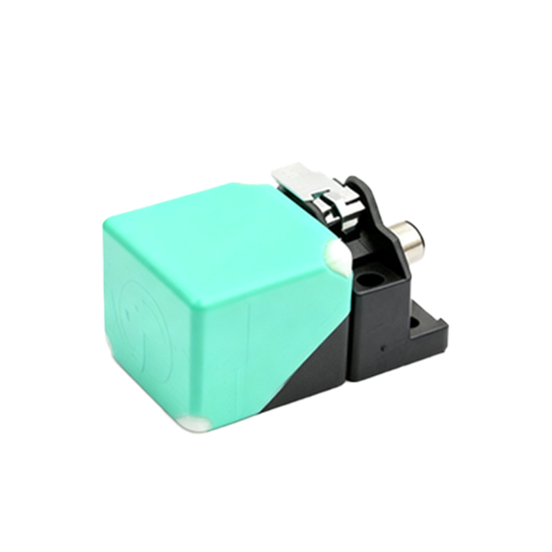
These sensors detect metallic objects. The base symbol is typically a diamond or square with the letters 'LI' or 'I' inside or adjacent. The symbol includes two main parts: the sensor itself and its output switch. The output is usually represented as a load switch (like a transistor) within the same enclosure symbol. In ladder diagrams, an inductive proximity sensor is often drawn as a normally open (NO) or normally closed (NC) contact with the abbreviation 'PROX' or a specific part number. The schematic will clearly show the connection points: typically, brown wire for DC positive (+V), blue for DC common (0V), and black for the switched output signal. A shield wire, if present, may be shown as a dashed line.
Capacitive Proximity Sensor Symbols
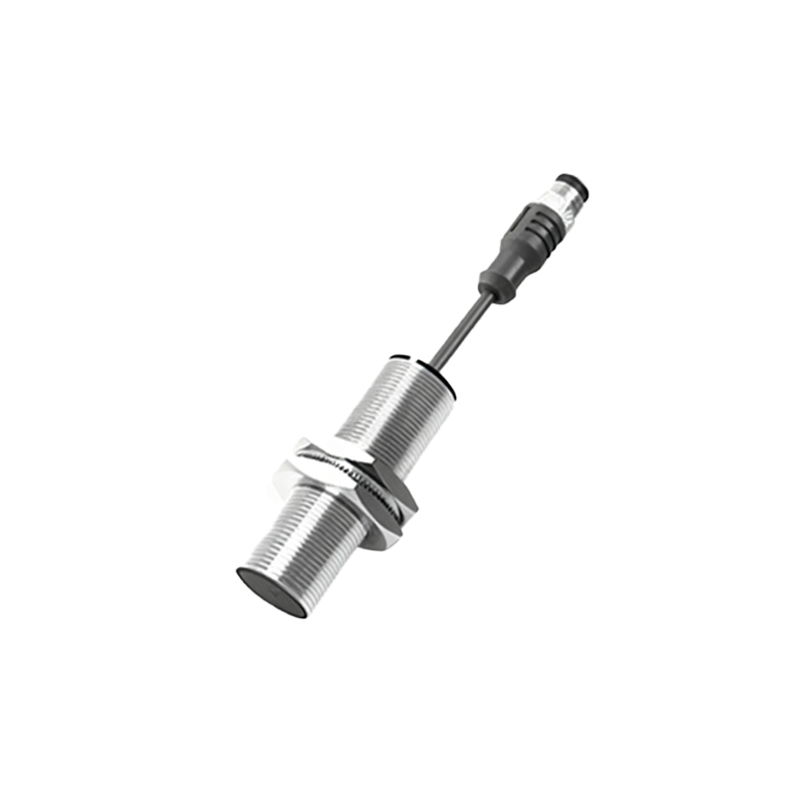
Capacitive sensors can detect both metallic and non-metallic materials (plastics, liquids, wood). Their symbol closely resembles the inductive one but is distinguished by the letters 'CA' or 'C'. In some schematics, two parallel lines (representing capacitor plates) are added to the diamond shape. The wiring diagram is similar to the inductive type, with power and output terminals. The key difference in the symbol is the identifier, alerting the designer or technician to its material detection capability.
Photoelectric Sensor Symbols
Photoelectric sensors use light beams for detection. Their symbol is more illustrative. The base is often a circle or a square with a circle inside. Two inward-pointing arrows (representing the transmitted and received light) are a universal indicator. For through-beam types, the symbol may be split into two parts: a transmitter (shown as a circle with an arrow pointing away) and a receiver (a circle with an arrow pointing in). Retro-reflective and diffuse sensors might use a single enclosure symbol with both arrows. The letters 'PE' or 'BEAM' are common identifiers. Output switching symbols are integrated similarly.
Magnetic Proximity Sensor (Reed Switch) Symbols
These are used with permanent magnets, often in cylinder position detection. The symbol frequently depicts a simple switch representation (like a normally open contact) enclosed in a circle or diamond, with a small magnet drawn nearby or the Greek letter 'Phi' (Φ) to indicate magnetism. They are sometimes labeled 'REED'.
Output Type Designations
The sensor symbol must also convey the output state. This is critical. A PNP (sourcing) output is often symbolized by the switch connected to the positive voltage line, while an NPN (sinking) output shows the switch connected to the common/negative line. The switch itself can be depicted as a standard electrical contact or a transistor symbol. For analog output sensors (e.g., 4-20mA), the symbol may include a small circle with an 'A' or a current loop indicator. Namur (intrinsically safe) sensors have a distinct symbol, often involving two crossing lines within the enclosure.
Schematic Representation in Circuits
In a full electrical schematic, the proximity sensor is not just a standalone symbol. Its power supply connections are drawn from the control voltage source. Its output wire connects to the input module of a PLC (Programmable Logic Controller) or directly to a relay coil. The accompanying legend or bill of materials will specify the exact model. In pneumatic circuit diagrams (to ISO 1219 standards), a proximity sensor detecting a cylinder piston position is shown as a small square with a diagonal line, connected to the cylinder with a dashed pilot line.
Key Markings and Labels
Beyond the core shape, look for these markings on or near the symbol:
- NO/NC: Denotes the normal electrical state of the output contacts without a target present.
- +/-: Polarity markings for DC sensors.
- AC: A sine wave symbol for alternating current sensors.