Hall effect sensors have become integral components in modern electronics, enabling precise detection of magnetic fields and proximity without physical contact. Among various types, proximity Hall sensors offer unique advantages for position sensing, speed measurement, and object detection applications. This experiment guide provides a hands-on approach to understanding the operational principles and practical implementation of proximity Hall sensors.
To begin the experiment, gather essential components: a Hall effect sensor module (such as the A3144 or SS49E), a permanent magnet, a microcontroller (Arduino Uno recommended), connecting wires, a breadboard, and an LED indicator. The Hall sensor operates on the principle that when a magnetic field perpendicular to the sensor’s surface is applied, it generates a voltage difference across its output terminals. This voltage, known as the Hall voltage, varies proportionally with the magnetic field strength.
Start by connecting the sensor to the microcontroller. Most Hall sensor modules have three pins: VCC (power supply), GND (ground), and OUT (signal output). Connect VCC to the 5V pin on the Arduino, GND to the ground pin, and OUT to a digital input pin (e.g., pin 2). Attach an LED to another digital pin (e.g., pin 13) through a current-limiting resistor (220 ohms). This setup allows the LED to visually indicate when the sensor detects a magnetic field.
Upload a simple code to the Arduino to read the sensor’s output. The code should set the sensor pin as an input and the LED pin as an output. In the loop function, read the sensor’s state: if it detects a magnetic field, the output goes LOW (or HIGH, depending on the sensor’s active state), triggering the LED to turn on. Otherwise, the LED remains off. This basic program demonstrates the sensor’s binary response to magnetic proximity.
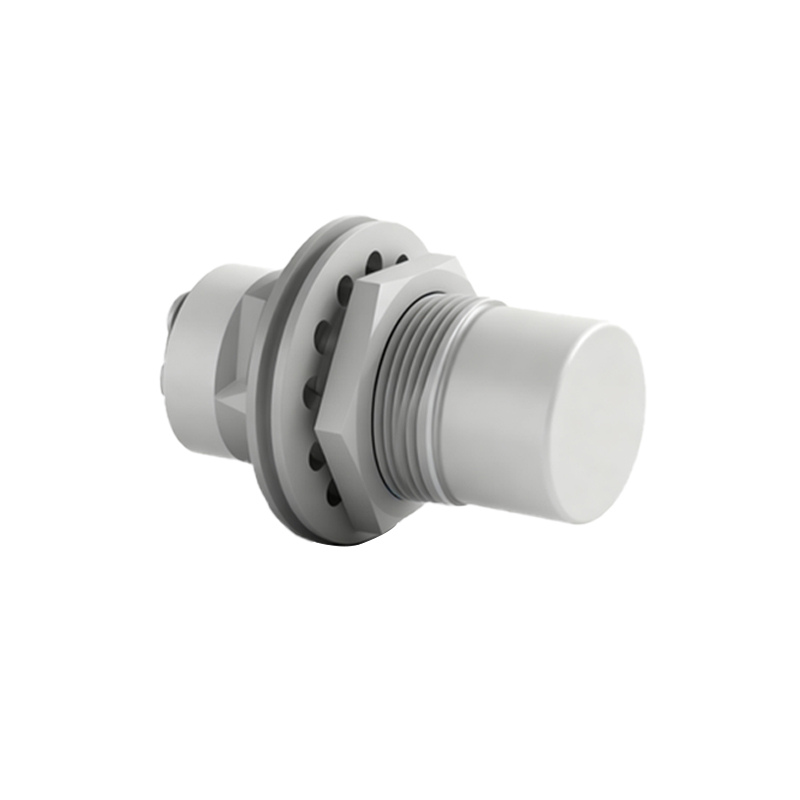
Next, experiment with varying distances between the sensor and the magnet. Move the magnet closer to the sensor and observe the point at which the LED activates. Record this distance as the detection threshold. Repeat the process with different magnet strengths or orientations to understand how these factors influence sensitivity. For analog Hall sensors, replace the digital read with an analog read to measure continuous voltage changes, providing data on magnetic field intensity relative to distance.
Applications of proximity Hall sensors extend beyond simple detection. They are widely used in automotive systems for wheel speed sensing, in industrial machinery for position feedback, and in consumer devices like smartphones for flip cover detection. The experiment can be expanded by integrating multiple sensors to track object movement or by adding a buzzer for audible alerts.
Key considerations during experimentation include minimizing electrical noise, ensuring stable power supply, and calibrating the sensor for specific environments. Temperature variations can affect sensor performance, so testing under different conditions provides insight into real-world reliability. Document all observations, including response times, detection ranges, and any inconsistencies, to build a comprehensive understanding of sensor behavior.
In conclusion, this hands-on experiment with proximity Hall sensors offers valuable insights into their functionality and versatility. By systematically testing parameters and exploring applications, users gain practical knowledge applicable to robotics, automation, and electronic design projects. The simplicity of the setup combined with the sensor’s robust performance makes it an excellent educational tool for students and hobbyists alike.