Proximity sensors are integral components in countless modern devices, from smartphones and tablets to industrial machinery and automotive systems. These non-contact sensors detect the presence or absence of an object within a specific range, enabling features like automatic screen dimming, touchless controls, and collision avoidance. When a proximity sensor malfunctions, it can disrupt core functionalities. This guide provides a systematic, practical approach to diagnosing and repairing common issues in modern inductive, capacitive, and photoelectric proximity sensors.
Before any repair, safety is paramount. Always disconnect the device from any power source. For industrial sensors, lock out and tag out the energy supply. Use appropriate personal protective equipment. Gather essential tools: a multimeter, soldering iron, fine-tip screwdrivers, isopropyl alcohol, lint-free cloths, and a magnifying glass or microscope for inspecting small components.
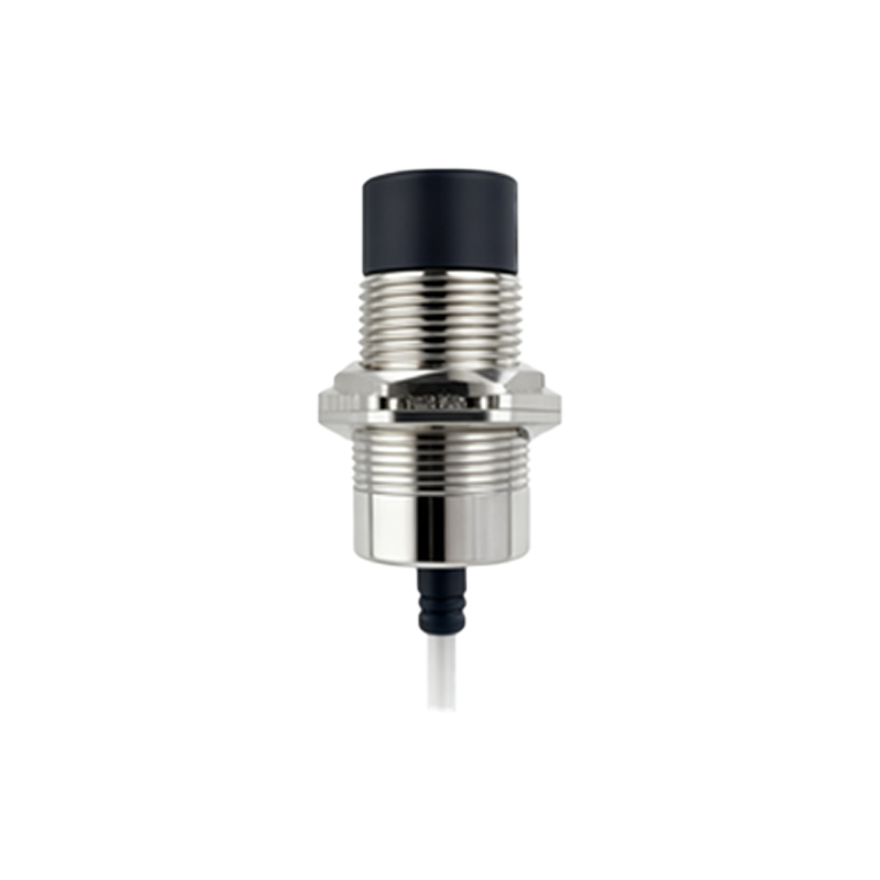
The first step is accurate diagnosis. Symptoms of a faulty sensor include erratic behavior, failure to detect objects, constant activation, or no response at all. Begin with a visual inspection. Look for obvious physical damage—cracks on the sensor face, bent housings, or corroded connectors. Clean the sensor's sensing face thoroughly with isopropyl alcohol to remove dirt, grease, or debris that could interfere with its operation.
Next, perform electrical testing with a multimeter. For a three-wire DC sensor (common in many applications), identify the power (brown/+), ground (blue/-), and output (black) wires. With power disconnected, check for continuity between the ground and power terminals to rule out a short circuit. Reconnect power according to the sensor's datasheet specifications. Measure the voltage between power and ground to ensure it is stable and matches the rated voltage (e.g., 12-24V DC).
To test the output, bring a metal target (for inductive sensors) within the specified sensing range. Use the multimeter in voltage mode to measure between the output wire and ground. A PNP (sourcing) sensor should show near supply voltage when inactive and drop to near 0V when activated. An NPN (sinking) sensor will show the opposite. No change indicates a potential sensor failure. For capacitive sensors, test with the appropriate dielectric material; for photoelectric sensors, ensure the light beam is unobstructed and the receiver is functional.
If electrical tests fail, internal inspection may be necessary. Carefully open the sensor housing, noting the arrangement of components. The core elements typically include an oscillator coil (inductive), a capacitor plate (capacitive), or an LED/phototransistor pair (photoelectric), along with a signal conditioning IC. Use the magnifying tool to inspect for burnt components, cracked solder joints, or damaged traces on the circuit board. A common point of failure is the output transistor, which can be tested in-circuit with a multimeter's diode mode or desoldered for further testing.
Repair involves targeted component replacement. If you find a bad solder joint, reflow it with a fine-tip soldering iron. For a damaged surface-mount component like a resistor or IC, carefully desolder the old part using appropriate techniques to avoid pad damage. Replace it with an identical component, matching specifications exactly. When replacing the sensing element itself (e.g., the coil), ensure precise alignment as per the original design. After any soldering, clean the board with isopropyl alcohol to remove flux residue.
Reassembly is critical. Ensure all seals are intact, especially for sensors rated IP67 or higher. Misalignment can drastically affect performance. Once reassembled, repeat the electrical and functional tests. Calibrate the sensor if required, using the manufacturer's procedure, to ensure it triggers at the correct distance.
Preventive maintenance can avoid future failures. Regularly clean the sensor face, check wiring for fraying or corrosion, and ensure the operating environment is within specified temperature, humidity, and voltage limits. Avoid exposing sensors to chemicals or physical impacts beyond their ratings.
While many sensor issues are repairable with patience and skill, some scenarios—like a damaged proprietary ASIC or a hermetically sealed unit—may necessitate complete replacement. Understanding these repair principles empowers technicians to restore functionality efficiently, saving cost and reducing downtime in both consumer electronics and industrial automation systems.