Understanding the Basics of Tracking Photoelectric Sensors
As a senior electrical engineer in industrial automation, I often encounter applications where precise object tracking along a defined path is critical. A tracking photoelectric sensor, commonly known as a line-following sensor, operates by emitting light—typically infrared or visible red—and detecting the reflected intensity from a surface. The key principle is the contrast between the track (e.g., a black line on a white background) and the surrounding area. When the sensor moves over the track, the reflectance changes, triggering a digital or analog output. For engineers, selecting the right sensor depends on factors like sensing distance, ambient light immunity, and response speed. In high-speed conveyor systems, for instance, a sensor with a fast switching frequency (e.g., 1 kHz or higher) is essential to avoid missed detections. Always verify the sensor's datasheet for response time and repeatability specifications.
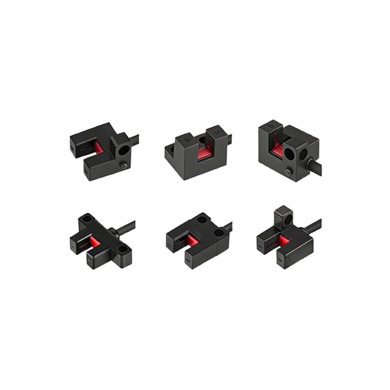
Key Selection Criteria for Industrial Environments
In my field experience, the most common failure points are due to environmental interference. For a tracking photoelectric sensor deployed in a factory floor with oil mist, dust, or vibration, you must prioritize IP67 or higher enclosure ratings. Additionally, consider the light source: laser-based sensors offer higher precision for fine tracking (down to 0.1 mm), but they are more sensitive to surface irregularities. For robust applications like AGV (Automated Guided Vehicle) navigation, I recommend diffuse reflective sensors with adjustable sensitivity. This allows fine-tuning to compensate for aging tape or varying floor colors. Another critical parameter is the sensing beam angle; a narrow beam (e.g., 5 degrees) is ideal for sharp turns, while a wider beam (e.g., 15 degrees) suits straight paths. Always perform a on-site test with the actual target material to confirm reliable triggering.
Installation and Calibration Best Practices
Proper installation is as important as component selection. I advise mounting the sensor at a consistent height from the tracking surface, typically between 5 mm and 30 mm, depending on the sensor's specified range. Use a rigid bracket to minimize vibration-induced misalignment. For calibration, start with the sensor's potentiometer or digital interface to set the threshold. A common technique is to place the sensor over the background (e.g., white surface) and adjust until the output just switches off, then move to the track (e.g., black line) and verify it switches on. In multi-sensor arrays for complex paths, ensure each sensor’s output is synchronized to avoid signal conflicts. I also recommend periodic cleaning of the lens—weekly for dusty environments—using a lint-free cloth and isopropyl alcohol to maintain accuracy.
Troubleshooting Common Issues in Field Applications
Even with careful planning, issues arise. A frequent problem is false triggering due to reflective floor coatings or glossy tape. To mitigate this, use a sensor with a polarized lens or switch to a background suppression model. Another challenge is inconsistent detection over corners; this often indicates the sensor's response time is too slow for the movement speed. As a rule of thumb, the sensor's maximum scanning rate (e.g., 2000 Hz) should be at least double the expected line crossing frequency. If you encounter drift over time, check for temperature-induced output changes—many industrial sensors have a compensation range of -25°C to +55°C. Logging output signals with a PLC can help isolate intermittent faults. Always keep spare sensors on hand, as replacement is faster than repairing damaged optics.
Integration with PLC and Control Systems
For seamless integration, the tracking photoelectric sensor's output must match your control system's input requirements. Most industrial sensors provide NPN (sinking) or PNP (sourcing) configurations; I prefer PNP for compatibility with modern PLCs like Siemens or Allen-Bradley. In high-noise environments, use shielded twisted-pair cables and connect the shield to ground at one end only to prevent ground loops. For advanced applications, analog output sensors (e.g., 0-10 V or 4-20 mA) can provide proportional position data, which is useful for fine-tuning AGV steering. When programming the PLC, implement a debounce timer (e.g., 5 ms) to filter out electrical noise. Testing with a simulated track at maximum speed ensures the system meets production throughput targets.