1. Introduction to Photoelectric Sensor Composition
A photoelectric sensor is a critical component in industrial automation, used to detect objects, distances, or presence without physical contact. Its composition can be understood through a detailed diagram that highlights key internal and external parts. This article breaks down the typical structure of a photoelectric sensor, focusing on the emitter, receiver, optics, housing, and signal processing unit.
2. Emitter and Light Source
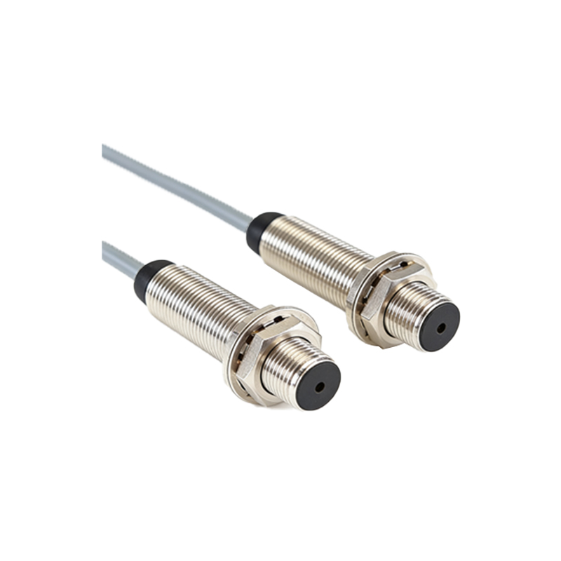
The emitter is the core component that generates the light beam. It typically consists of a light-emitting diode (LED) or laser diode, which emits infrared, visible red, or ultraviolet light depending on the application. The emitter is housed in a sealed compartment to prevent contamination and is often paired with a lens to focus the beam. In the diagram, the emitter is usually located at the front of the sensor, with arrows indicating the direction of the light output.
3. Receiver and Photodetector
Opposite the emitter, the receiver contains a photodetector, such as a photodiode or phototransistor. This component converts incoming light into an electrical signal. In the diagram, the receiver is often shown as a sensitive area behind a window or lens. For through-beam sensors, the receiver is separate from the emitter; for retro-reflective or diffusive types, they are integrated into the same housing. The photodetector’s sensitivity is calibrated to distinguish between the presence and absence of the target object.
4. Optics and Lens System
The optics system includes lenses, filters, and sometimes a prism or mirror. Lenses shape and focus the light beam, ensuring optimal detection range and accuracy. In the composition diagram, lenses are depicted as curved elements near the emitter and receiver. Some sensors include a polarizing filter to reduce false triggers from reflective surfaces. For retro-reflective sensors, the diagram includes a reflector element that bounces the beam back to the receiver.
5. Housing and Environmental Protection
The housing encloses all internal components and provides mechanical strength and environmental protection. Materials like stainless steel or reinforced plastic are common. The diagram shows the housing as a rectangular or cylindrical outer shell, often with an IP (Ingress Protection) rating label. Seals and gaskets prevent dust and moisture ingress. A mounting bracket or thread is also visible in the diagram, facilitating installation in industrial machinery.
6. Signal Processing and Output Circuitry
Inside the housing, the signal processing unit interprets the photodetector’s output. This includes an amplifier, comparator, and Schmitt trigger circuit to clean the signal. The diagram typically shows these as a small board or chip near the receiver. The output circuitry provides standard industrial signals like NPN/PNP, relay, or analog voltage. A potentiometer or push-button adjustment for sensitivity is often indicated in the diagram with a symbol.
7. Power Supply and Connectors
The sensor requires a stable power supply, usually 10-30 VDC for industrial types. The diagram includes a power input terminal or cable, along with a connector for quick disconnection. Some sensors feature LED indicators for power and output status, shown as small circles near the connector. The wiring diagram part of the composition illustrates color-coded wires for Vcc, GND, and output.
8. Additional Features: Timer and Diagnostics
Advanced photoelectric sensors include a timer module for delay-on or delay-off functions, and diagnostic LEDs for alignment and fault indication. In the diagram, these are represented as additional blocks connected to the signal processor. A test input pin or manual test button may also be present, allowing users to simulate detection for setup verification.
9. Conclusion: Interpreting the Diagram for Application
Understanding the composition of a photoelectric sensor through its diagram helps engineers select the right model for specific tasks. By analyzing the emitter, receiver, optics, housing, and signal processing, one can predict performance in harsh environments, detectability of target materials, and integration with control systems. Always refer to the manufacturer’s diagram for precise component layout and ratings.