Understanding the Role of Photoelectric Sensors in Industrial Automation
Photoelectric sensors are critical components in modern manufacturing and process control systems. They detect the presence, absence, or distance of objects using light beams, typically in the visible or infrared spectrum. When a sensor fails, it can cause production line stoppages, quality defects, or safety hazards. As an electrical engineer with over 15 years of field experience, I have encountered numerous sensor failures, and understanding their operating principles—through-beam, reflective, and diffuse modes—is essential for effective troubleshooting.
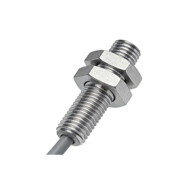
Common Signs of a Faulty Photoelectric Sensor
A failing photoelectric sensor often exhibits specific symptoms before complete breakdown. Look for erratic output signals, such as false triggers or missed detections, especially in dusty or humid environments. Another sign is a slow response time; if the sensor takes longer to change its output state when the target enters or leaves the detection zone, the internal LED or phototransistor may be degrading. Physical inspection may reveal cracked lenses, water ingress, or corroded connectors. If the equipment shows intermittent stops or random alarms, start by checking the sensor’s power supply voltage and alignment.
Step-by-Step Troubleshooting Procedure
Begin by verifying the power source. Use a multimeter to confirm the sensor receives its rated voltage, typically 10-30 VDC for industrial models. Next, clean the lens with a lint-free cloth and isopropyl alcohol to remove oil or debris. Then, perform a beam alignment test. For through-beam sensors, ensure the emitter and receiver are perfectly aligned; use a laser pointer if needed. For reflective sensors, check if the reflector is clean and correctly positioned. If the sensor still fails, test it with a known-good target or swap it with a spare unit. Record the sensor model and configuration before replacement.
Common Failure Modes and Root Causes
Photoelectric sensor failures are often due to environmental factors. Excessive vibration can crack internal solder joints, while high-temperature environments may degrade the plastic lens. Electrical surges from nearby motors or welding equipment can damage the output transistor. Another frequent issue is contamination: metal shavings, coolant, or dust can block the light path. In diffuse sensors, the sensing distance may decrease over time as the LED output dims. Understanding these root causes helps in selecting more robust sensors, such as those with high ingress protection ratings (IP67 or higher) for harsh environments.
Best Practices for Sensor Replacement
When replacing a faulty photoelectric sensor, always consult the manufacturer’s datasheet for correct wiring and setup. Use a sensor of the same or equivalent electrical and mechanical specifications—matching output type (NPN vs. PNP), sensing range, and response time. For critical applications, consider using a sensor with diagnostic features, such as a visible alignment indicator or IO-Link communication. After installation, perform a final functional test: verify the sensor correctly switches under all operating conditions, including with varying target materials and ambient light. Document the replacement in the maintenance log for future reference.
Conclusion: Preventive Maintenance for Long Service Life
To minimize future sensor failures, implement a regular preventive maintenance schedule. This includes quarterly lens cleaning, annual alignment checks, and periodic verification of response times. Consider upgrading to sensors with built-in self-diagnostics or redundant outputs for high-reliability lines. By following these engineering best practices, you can significantly reduce unplanned downtime and extend the lifespan of your photoelectric sensors.