Understanding Photoelectric Sensor Thresholds
In industrial automation, photoelectric sensors are critical for detecting objects, distances, and material properties. The threshold value defines the sensitivity level at which the sensor triggers an output. Setting this correctly ensures reliable operation, reduces false triggers, and improves process efficiency. For example, in a conveyor system, a poorly set threshold may miss transparent objects or cause false alarms due to ambient light. Engineers must calibrate threshold based on target reflectivity, background interference, and environmental conditions. A common approach is to use a teach-in function, which automatically captures the optimal value during a reference run. However, manual adjustment remains necessary in harsh or variable environments, such as dusty factories or high-vibration areas.
Factors Influencing Threshold Selection
Several key factors affect threshold setting for photoelectric sensors. First, the sensor type plays a role: through-beam sensors have high stability and require a threshold near the clear signal level, while diffuse sensors need adjustment for target color and surface. Second, background suppression is essential in applications with overlapping objects, such as in packaging lines where shiny and matte surfaces coexist. Third, ambient light and temperature drift can shift the baseline signal; for instance, in outdoor installations, sunlight may saturate the receiver. Engineers should also consider sensor response time and output type (e.g., NPN or PNP) to match controller requirements. Using a threshold that is too low increases sensitivity to noise, while a too-high threshold may cause missed detections. A practical rule is to set the threshold at 50-70% of the maximum signal range for moderate reliability, but for critical safety systems, a hysteresis band of 5-10% is recommended to avoid oscillation.
Step-by-Step Threshold Calibration Process
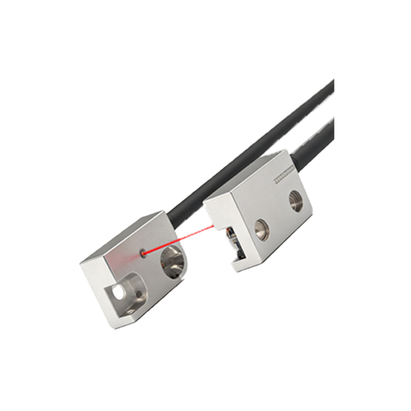
To calibrate the threshold value, follow this structured procedure. First, mount the sensor securely and align it with the target path. Next, expose the sensor to the target object at the expected distance and note the signal level. For a teach-in sensor, press the button to capture the threshold; manual sensors require a potentiometer adjustment. Then, test with no target present to measure background signal. Adjust the threshold to a midpoint between these two levels, ensuring a minimum margin of 20% to compensate for drift. In dynamic applications, such as high-speed sorting, use an oscilloscope to verify signal stability. Finally, validate the setting over 100 cycles to confirm no false triggers. Document the final threshold value and environmental conditions for future maintenance.
Common Pitfalls and Troubleshooting
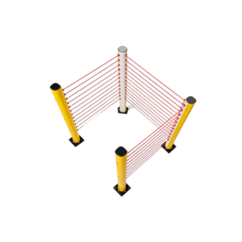
Even with careful setup, threshold issues arise in practice. A frequent problem is signal saturation due to reflective backgrounds, such as metallic surfaces behind a target. Solution: use a background suppression sensor or adjust the threshold to ignore low-reflectivity zones. Another pitfall is signal noise from power line interference, which can cause erratic triggering. Engineers should install shielded cables and use a threshold with hysteresis. For transparent object detection, like glass bottles, set a lower threshold to capture partial reflection, but test against ambient light changes. Always perform a worst-case scenario test, such as reduced power or dust accumulation, to ensure robustness. If problems persist, consider upgrading to a laser-based sensor for higher precision.
Advanced Techniques for Complex Environments
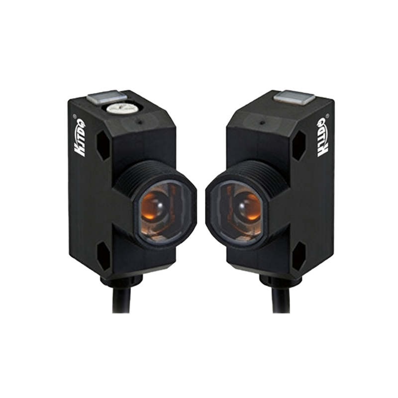
In complex industrial settings, standard threshold methods may fail. For example, in cleanrooms with critical alignment, use dual-threshold logic to distinguish between stable and transient signals. In wet or corrosive environments, choose sensors with IP67 ratings and set thresholds to ignore water droplets. For high-speed lines, such as in automotive assembly, implement a dynamic threshold that adapts to speed variations via a PLC input. Another technique is frequency modulation, where the sensor’s emitter pulses at a specific rate to reject ambient light. Engineers can also use software-filtered thresholds, where the sensor averages multiple samples to reduce noise. These advanced methods require deeper integration but significantly improve reliability in harsh conditions.