Introduction to Photoelectric Sensor Indicators
Photoelectric sensors are critical components in industrial automation systems, providing non-contact detection of objects, distances, and positions. The status indicators on these sensors, particularly green and orange LEDs, convey essential operational information. As an experienced electrical engineer, I will decode these signals to enhance your system diagnostics and troubleshooting efficiency. The green light typically signifies a stable, powered state or a successful sensing condition, while the orange light often denotes a transient or setup mode. Understanding these color codes is vital for maintaining system reliability and reducing downtime in manufacturing environments.
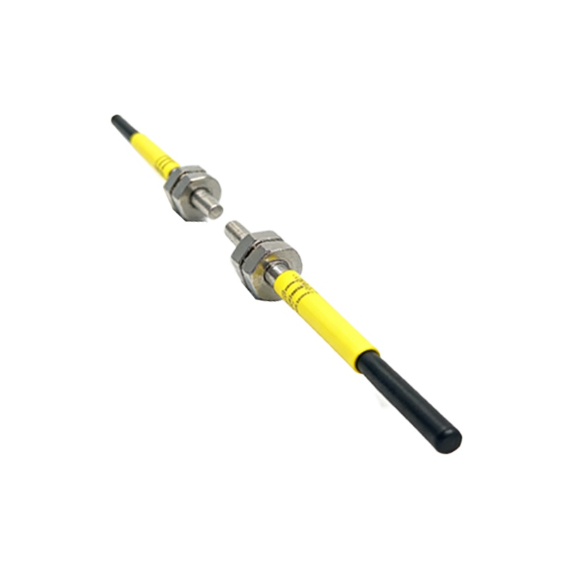
Green Light: Power and Normal Operation
In most photoelectric sensors, a steady green LED indicates that the sensor is properly powered and functioning within its normal operating parameters. This includes a stable supply voltage typically ranging from 10 to 30 VDC and a clean optical path. For instance, in through-beam sensors, green confirms the emitter and receiver are aligned. In diffuse reflective models, it signals consistent reflection from the target. Modern sensors from brands like Banner or SICK use green to represent a "ready" state, meaning all internal diagnostics are clear. If the green light flickers, it might indicate marginal power supply noise or a dirty lens, prompting preventive maintenance.
Orange Light: Alignment, Setup, or Marginal Detection

An orange LED on photoelectric sensors often indicates an auxiliary status, such as alignment mode, setup mode, or a marginal detection condition. During installation, many sensors switch to orange when entering a "teach" state, where the user adjusts sensitivity or distance thresholds. In some models, a constant orange light means the sensor is detecting an object but with a weak signal, perhaps due to a partially blocked lens or a target with low reflectivity. For example, in a retro-reflective sensor, orange might flash when the reflector is slightly misaligned. This serves as a warning to adjust the optical path before a full failure occurs.
Common Combinations: Green and Orange Together
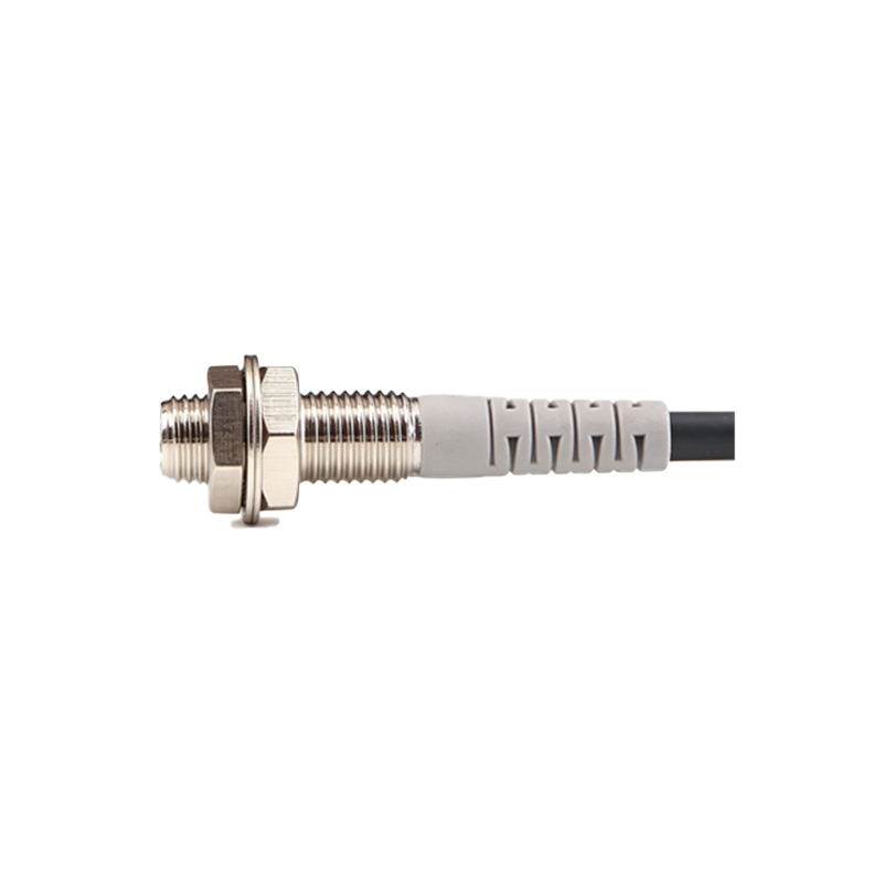
When both green and orange LEDs are illuminated simultaneously, it typically indicates a specific multi-functional state. For instance, many intelligent photoelectric sensors use this combination to show that the device is in a "locked" or "programmed" mode, where custom parameters are active. Alternatively, a green-amber transition during operation might suggest a change in ambient light conditions affecting the sensor. As an engineer, I recommend consulting the sensor's data sheet to interpret these combinations precisely, as manufacturers like Omron and Keyence often assign unique meanings to dual-color statuses.
Troubleshooting with LED Colors
To effectively troubleshoot using LED colors, follow a systematic approach. First, if the sensor shows a solid green, verify that the target is reaching the detection zone. If the orange light appears, check for potential issues: clean the lens, verify alignment, and test with a known good reflector or target. In harsh industrial environments with dust or vibration, orange may indicate intermittent power surges. For example, in a conveyor system, a flashing orange could signal a loose cable. Always integrate these visual cues with a multimeter or oscilloscope for precise electrical diagnostics to avoid unnecessary replacements.
Best Practices for Maintenance Based on Indicators
Regular maintenance should include a visual inspection of the LED indicators. A green light is reassuring, but I advise periodic calibration to ensure optimal performance. For sensors consistently showing orange, schedule a cleaning cycle or adjust mounting brackets to improve alignment. In advanced systems, use a PLC to log LED status changes over time, identifying trends like increasing orange frequency, which may predict imminent failure. By correlating these signals with environmental factors (e.g., temperature, humidity), you can implement predictive maintenance. This approach minimizes unplanned stops in critical applications like packaging or automotive assembly lines.
Conclusion: Enhancing System Reliability
Mastery of green and orange LED indicators on photoelectric sensors empowers electrical engineers to maintain robust automation systems. These colors are not arbitrary; they are part of a universal language for sensor health and performance. By applying the insights above—interpreting green as operational stability and orange as a cautionary state—you can reduce diagnostic time and improve overall equipment effectiveness (OEE). Always reference the manufacturer’s documentation for specific models, and integrate these visual cues with a comprehensive maintenance strategy. In the fast-paced world of industrial automation, this knowledge is key to sustaining high productivity.