What Is the Optical Axis in Photoelectric Sensors?
In the field of industrial automation, the optical axis is a fundamental concept for photoelectric sensors. It refers to the imaginary straight line that connects the center of the light source (emitter) to the center of the receiver (detector). This axis defines the primary path along which the light beam travels between the transmitter and the receiver in through-beam, retro-reflective, or diffuse sensors. In through-beam sensors, the optical axis must be precisely aligned to ensure the beam reaches the receiver without obstruction. In retro-reflective sensors, the axis is defined by the emitter-receiver pair and the reflector, while in diffuse sensors, the axis is determined by the emitter and the target surface. The alignment of the optical axis directly impacts sensor performance, including detection range, sensitivity, and reliability. Misalignment can lead to false triggers, reduced detection distance, or total failure. Engineers must consider the optical axis when mounting sensors in harsh environments with vibration, temperature fluctuations, or dust. For example, in conveyor belt systems, the optical axis must be perpendicular to the belt surface to detect objects accurately.
How the Optical Axis Affects Sensor Performance
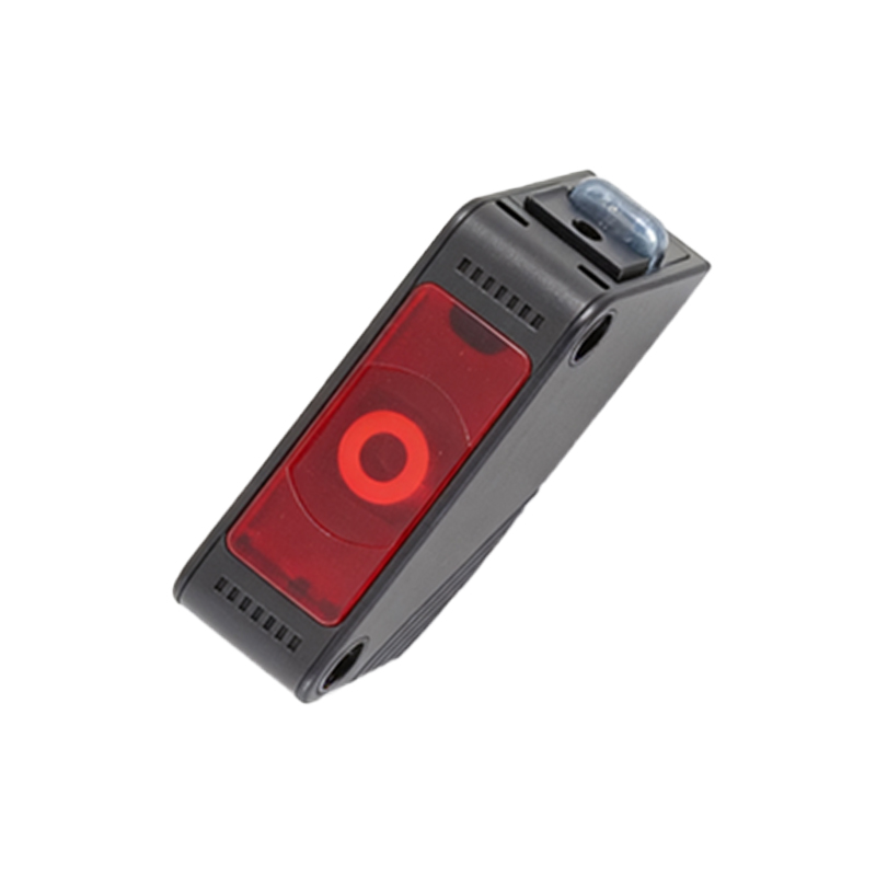
The optical axis determines the sensor's beam geometry, which includes beam divergence, spot size, and focal point. For laser-based photoelectric sensors, the optical axis is highly collimated, meaning the beam remains narrow over long distances, allowing precise detection of small targets. In contrast, LED-based sensors have a wider beam angle, which requires careful optical axis alignment to avoid stray light interference. The optical axis also influences the sensor's response time and hysteresis. If the axis is off-center, the sensor may exhibit slower response or inconsistent detection. In industrial settings, such as packaging lines or robotic assembly, maintaining the optical axis within tolerance is critical. For instance, a misaligned optical axis in a through-beam sensor can cause the beam to miss the receiver due to angular displacement, leading to machine stoppages. Engineers often use alignment tools like laser pointers or mechanical jigs to ensure the optical axis is straight. Additionally, environmental factors like fog, smoke, or condensation can scatter the beam, altering the effective optical axis. Therefore, sensor housings with anti-fog coatings or air-purge systems help stabilize the optical path.
Common Causes of Optical Axis Misalignment
Misalignment of the optical axis can stem from several sources. Mechanical vibration from nearby machinery, such as motors or pumps, can shift sensor mounts over time, causing the optical axis to drift. Temperature changes cause thermal expansion or contraction of sensor brackets, altering the alignment. Furthermore, improper installation, such as mounting sensors on flexible surfaces or using worn-out fasteners, allows the optical axis to deviate. In retro-reflective sensors, dirty or damaged reflectors can scatter light, effectively changing the optical axis direction. For diffuse sensors, the target surface angle affects the optical axis; a tilted target may reflect light away from the receiver. To mitigate these issues, engineers should use rigid mounting brackets, schedule regular maintenance, and apply alignment verification procedures. For example, in cleanroom environments, periodic laser alignment checks ensure the optical axis remains within 0.5 degrees of tolerance. Advanced sensors with self-alignment features, such as automatic calibration or optical feedback, are also available to compensate for minor misalignments.
Practical Tips for Optical Axis Alignment
To achieve optimal sensor performance, follow these alignment best practices. First, use a sighting tool or built-in alignment indicator to verify the optical axis before finalizing the sensor position. For through-beam sensors, mount both the emitter and receiver on a straight track or use a laser alignment tool. Second, ensure the sensor's beam is unobstructed by debris, oil, or condensation. Third, in environments with high ambient light, use filters or hoods to reduce interference that could distort the optical axis. Fourth, after initial installation, perform a dynamic test by moving a target along the detection path. If the sensor triggers inconsistently, realign the optical axis. For example, in a bottle-filling line, the optical axis must be perpendicular to the conveyor to detect bottles accurately. Fifth, document the alignment parameters, such as distance and angle, for future maintenance. Modern sensors often provide digital outputs indicating beam strength or alignment quality, which simplifies troubleshooting. By prioritizing optical axis alignment, engineers can reduce downtime and extend sensor lifespan.