Understanding the Two-Wire Photoelectric Sensor and Its 220V AC Power Supply
A 220V two-wire photoelectric sensor is a robust and cost-effective industrial detection device, commonly used in automation lines and conveyor systems. Unlike three-wire sensors, it operates on an alternating current (AC) supply of 220V, requiring only two wires for both power and signal output. The sensor's internal circuitry is designed to handle high voltage, making it ideal for applications where a separate DC power supply is not available. Its output is typically a normally open (NO) or normally closed (NC) switching contact, which responds to the presence or absence of an object. Electrical engineers must pay attention to the sensor's electrical characteristics, such as the maximum load current (usually around 200mA to 400mA) and the leakage current (often less than 3mA). This leakage current is a critical parameter; if the connected load has a high impedance, it may remain partially energized even when the sensor is in the off state. Therefore, always verify the sensor's datasheet to ensure compatibility with your specific PLC input module or relay coil.
Wiring Considerations and Load Matching for 220V AC Sensors
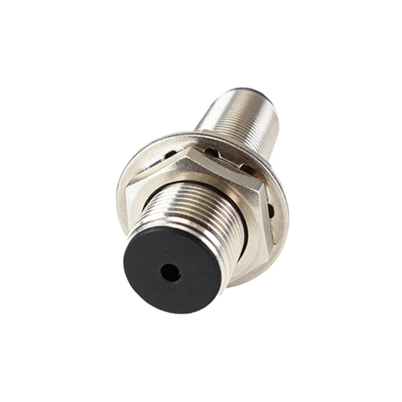
Proper wiring is essential for the reliable operation of a 220V two-wire photoelectric sensor. Since it is a series-connected device, it must be wired in series with the load (e.g., a contactor coil, a PLC input, or a relay). The total impedance of the load must be low enough to allow the sensor to switch correctly. A common mistake is connecting the sensor directly to a high-impedance input without a proper load resistor. If the load impedance exceeds 10k ohms, the sensor may not turn off completely due to the leakage current. In such cases, a R-C snubber circuit or a shunt resistor (typically 10k ohm, 5W) should be added in parallel with the load to absorb the leakage. Additionally, ensure the power supply is stable and within the specified voltage range (usually 200V to 240V AC). Use a dedicated circuit breaker and avoid sharing the power line with heavy inductive loads like large motors to prevent voltage spikes. Always use appropriately rated wire (e.g., 1.5mm²) and follow local electrical codes for strain relief and grounding.
Mounting and Environmental Factors Affecting Detection Accuracy
The physical installation of the sensor directly impacts its performance. For typical through-beam or retro-reflective sensors, align the emitter and receiver accurately, ensuring no physical obstructions. The sensing distance is rated for a standard target (e.g., a 100mm white paper for diffuse sensors). Real-world objects, especially dark or shiny surfaces, can reduce the effective range by 30% to 50%. Environmental factors like dust, oil, or vibration must be considered. Use the sensor's sensitivity adjustment pot (if available) to fine-tune the detection threshold. For outdoor or wet environments, choose a sensor with an IP67 rating. Also, avoid mounting the sensor near high-frequency or high-voltage cables to minimize electromagnetic interference (EMI). Using a shielded cable for the sensor's wires can further reduce noise, but ensure the shield is grounded only at one end to avoid ground loops.
Troubleshooting Common Faults in 220V Two-Wire Sensors
When a two-wire photoelectric sensor fails to operate correctly, follow a systematic diagnostic approach. First, check the power supply: measure the voltage at the sensor's terminals with a multimeter, ensuring it is 220V AC ±10%. If voltage is absent, inspect the circuit breaker and wiring continuity. Next, test the sensor's output by simulating an object. With a known resistive load (e.g., a 100W incandescent bulb) connected in series, observe if the bulb turns on and off. If the bulb remains dimly lit, the leakage current is too high for the load. In this case, add a load resistor as described earlier. If the sensor does not switch at all, the internal electronics may be damaged due to voltage spikes or moisture. Also, verify that the target object is within the specified sensing range and has the correct reflective properties. For retro-reflective sensors, clean the reflector or retro-tape regularly. Finally, use an oscilloscope to check for noise on the AC line; if present, install a line filter.