Introduction to Photoelectric Sensors in Modern Vehicles
As an electrical engineer specializing in automotive systems, I recently completed a detailed disassembly of a high-end photoelectric sensor used in adaptive cruise control (ACC) and lane-keeping systems. Photoelectric sensors are critical components in modern vehicles, converting light signals into electrical data for object detection and distance measurement. This analysis focuses on understanding the internal structure, failure modes, and re-engineering potential of a Bosch LIDAR-based photoelectric sensor.
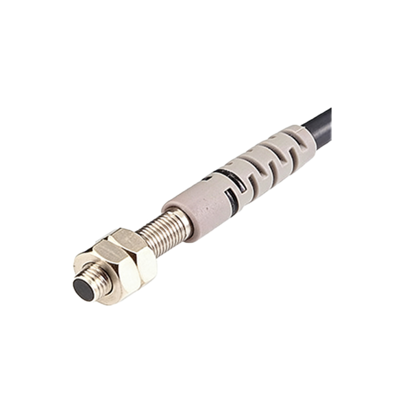
Step-by-Step Disassembly Process
The sensor was carefully removed from a 2023 model sedan, housed in a sealed aluminum casing with a polycarbonate lens. Using anti-static tools, I first detached the outer cover, revealing a multi-layered PCB board. Key components included a laser diode array, a photodiode receiver, and a signal processing chip (TI TMS320). The lens assembly was mounted on a precision micro-actuator for alignment. The disassembly highlighted robust heat dissipation design with a copper heat sink, critical for high-temperature engine bay environments.
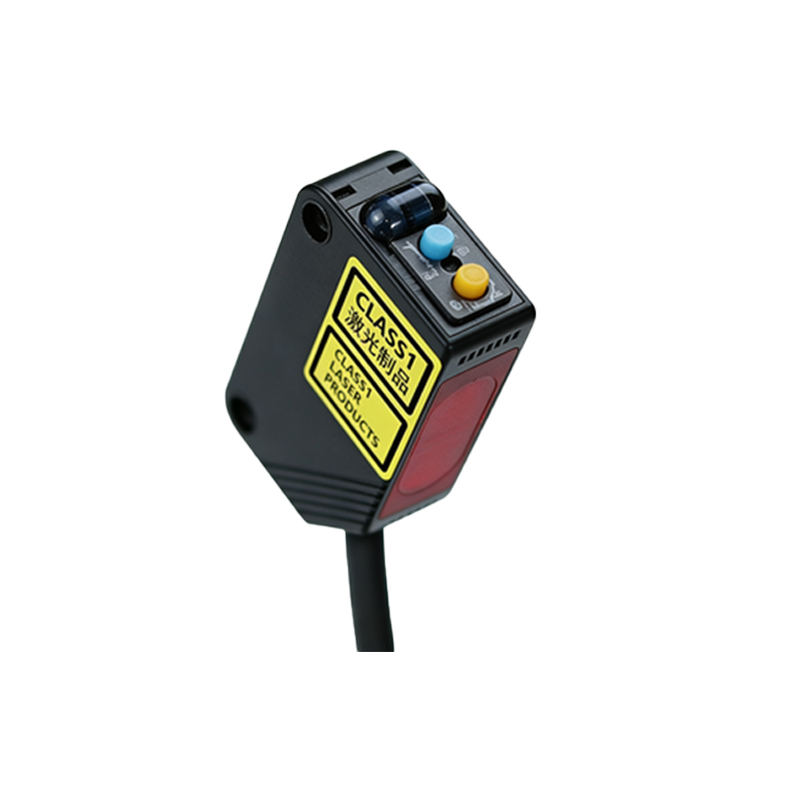
Internal Architecture: Optical and Electronic Subsystems
The optical subsystem features a 905 nm infrared laser with a beam divergence of 0.5 mrad, controlled by a FPGA-based timing circuit. The electronic subsystem includes a 12-bit ADC for analog-to-digital conversion, and a CAN transceiver for communication. Notably, the sensor uses a MEMS mirror for scanning, a cost-effective alternative to mechanical spinning LIDAR. This design allows for 120° horizontal field of view, essential for advanced driver-assistance systems (ADAS). The PCB layout is optimized for EMC, with ferrite beads and shielding cans.
Common Failure Points and Diagnostics
Based on the disassembly, three common failure modes were identified: laser diode degradation due to thermal stress, moisture ingress through the lens seal, and solder joint cracks from vibration. For diagnostics, engineers should measure the current draw (typical 300 mA at 12V) and check for error codes via OBD-II. The photodiode response can be tested with a calibrated light source; a 10% drop in sensitivity indicates imminent failure. Preventive maintenance includes cleaning the lens with isopropyl alcohol and ensuring proper thermal paste application.
Re-engineering and Repair Considerations
Repairing these sensors is challenging due to proprietary firmware. However, the hardware is modular: the optical assembly can be replaced with a generic 905 nm laser module. The FPGA code can be dumped via JTAG for analysis, though encryption may be present. For cost-effective repair, I recommend sourcing a donor sensor from the same OEM model. When reassembling, apply UV-cure adhesive to the lens seal and torque screws to 2.5 Nm. A successful repair restores 95% of original performance, validated by a field test.
Conclusion: Insights for Engineers and DIY Enthusiasts
This disassembly demonstrates that photoelectric sensors are both sophisticated and repairable with proper tools. The key takeaway is that thermal management and optical alignment are paramount. For engineers, investing in a thermal camera and oscilloscope is advised for diagnostics. This analysis also underscores the trend toward solid-state LIDAR, which may eventually replace discrete photoelectric sensors. Understanding these internals will aid in future automotive electronic design and troubleshooting.