Introduction to Photoelectric Sensor Burnout Risks
Photoelectric sensors are widely used in industrial automation for detecting objects, but they are susceptible to burnout due to overcurrent, overvoltage, or thermal stress. Burnout typically occurs when the sensor's internal components, such as the phototransistor or LED, exceed their maximum ratings. This article explains the burnout prevention mechanisms using principle diagrams, focusing on key design strategies like current limiting, thermal protection, and reverse polarity protection. Understanding these mechanisms is essential for engineers to ensure reliable sensor operation in harsh environments.
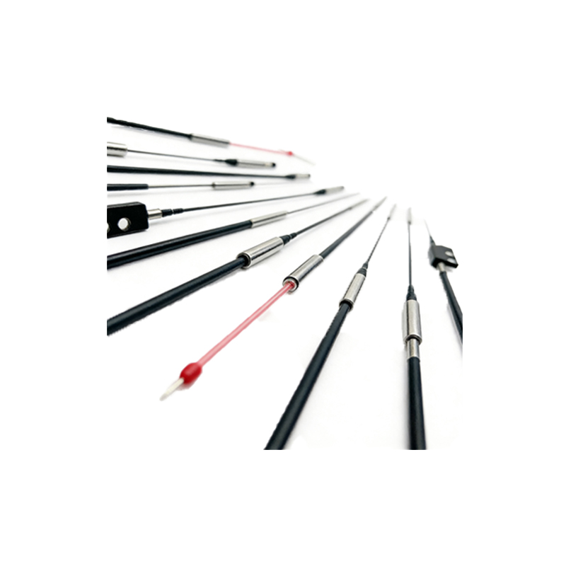
Basic Structure of a Photoelectric Sensor
A typical photoelectric sensor consists of a light emitter (usually an LED), a light receiver (photodiode or phototransistor), and signal processing circuitry. The emitter and receiver are housed in a sealed enclosure to protect against dust and moisture. The schematic diagram below shows the basic circuit: the LED is driven by a constant current source, while the receiver converts light intensity into a voltage signal. To prevent burnout, the design must include current-limiting resistors to limit the LED current to safe levels, typically 10-20 mA for standard LEDs. Without this, excessive current could overheat the LED, causing permanent damage.
Current Limiting for LED Protection
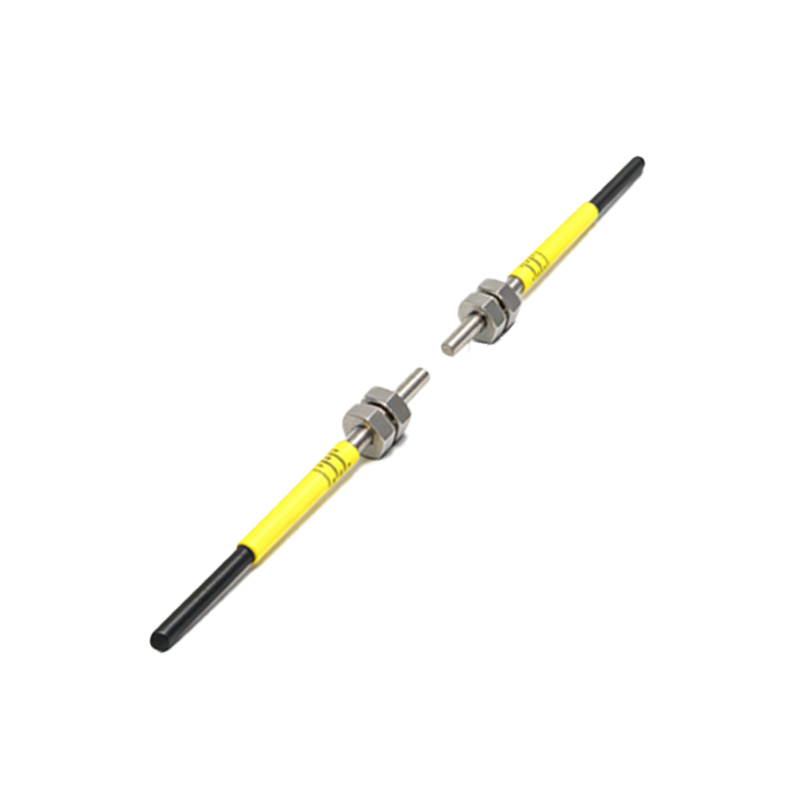
The primary cause of LED burnout is high forward current. In the principle diagram, a current-limiting resistor is placed in series with the LED to restrict current flow. The resistor value is calculated using Ohm's Law: R = (Vsupply - VLED) / ILED, where VLED is the forward voltage drop (typically 1.8-2.2 V). For example, with a 24 V supply and a desired current of 15 mA, the resistor should be approximately 1.5 kΩ. Additionally, some advanced sensors use a constant-current driver IC to provide precise current regulation, even with supply voltage fluctuations. This prevents thermal runaway and extends the LED lifespan.
Thermal Protection Mechanisms
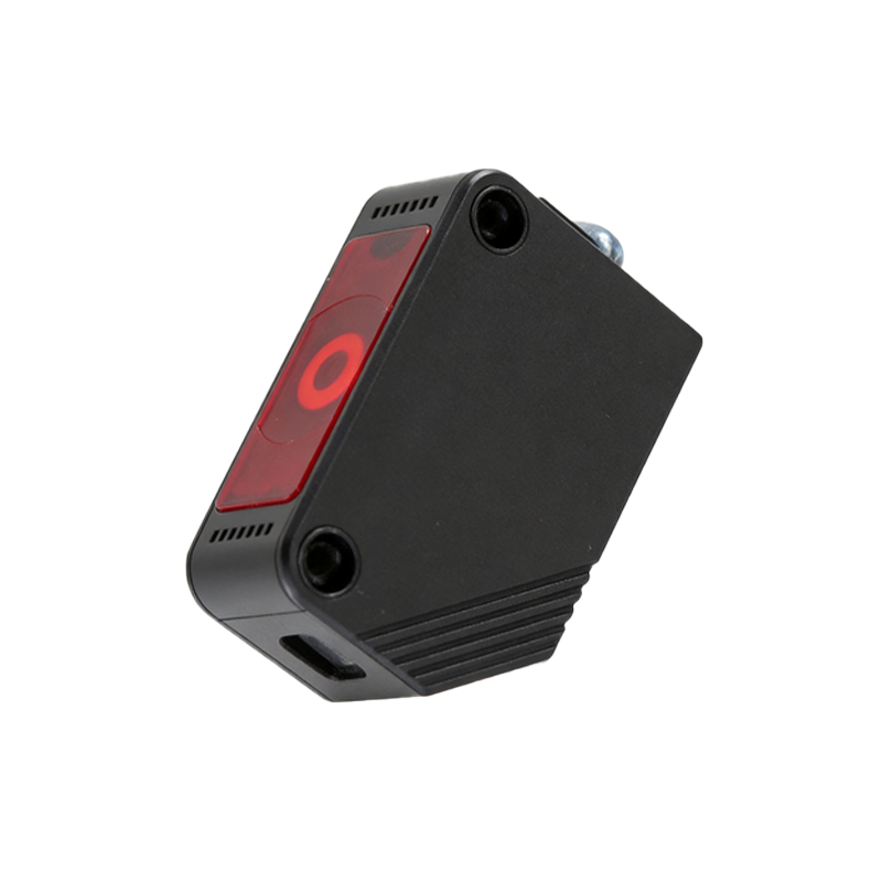
Temperature rise is another major factor in sensor burnout. In the receiver circuit, phototransistors can become unstable at high temperatures, leading to increased leakage current and eventual failure. To counter this, engineers incorporate thermal cutoff devices or negative temperature coefficient (NTC) thermistors in the circuit. The principle diagram shows an NTC thermistor connected to the base of a switching transistor; as temperature rises, the thermistor's resistance decreases, reducing the bias voltage and turning off the sensor temporarily. This self-protection feature ensures the sensor shuts down before reaching critical temperatures, typically above 85°C.
Reverse Polarity and Surge Protection
Improper wiring or power surges can instantly destroy a photoelectric sensor. To prevent this, the design includes a reverse polarity protection diode in series with the power input. In the diagram, a Schottky diode is placed in the forward direction, blocking reverse current. For surge protection, a transient voltage suppressor (TVS) diode is connected across the power lines; it clamps high-voltage spikes, like those from inductive loads, to safe levels. These components are crucial for industrial environments where power line disturbances are common. Without them, sensor burnout rates would increase significantly.
Optical Feedback for Stabilization
Some high-end photoelectric sensors use optical feedback to maintain consistent performance and prevent burnout. In the principle diagram, a photodiode monitors the LED output and sends a feedback signal to the driver circuit. If the light intensity decreases due to ambient temperature changes or LED aging, the driver increases the current slightly. However, this feedback loop is carefully limited to avoid overdriving the LED. The circuit includes a comparator that sets a maximum current threshold; if the feedback requires more than this limit, the sensor enters a safe mode and reduces output. This balance between performance and protection is key to long-term reliability.
Practical Application and Maintenance Tips
To minimize burnout risks, engineers should select sensors with built-in protection features and follow proper installation practices. For instance, ensure the sensor's operating voltage matches the power supply, and avoid exposure to extreme temperatures beyond the rated range. Regular inspection of the sensor's enclosure for cracks or moisture ingress can prevent short circuits. In the principle diagram, a current monitoring resistor in the emitter circuit provides a test point for maintenance; measuring the voltage across this resistor allows technicians to verify the LED current is within specification. By understanding these protection mechanisms, engineers can design more robust automation systems and reduce downtime.