2026-06-08
Tech Hub
By 创始人
Adjusting Photoelectric Sensors on Wire Bonding Machines: A Practical Guide
Understanding Photoelectric Sensor Basics in Wire Bonding
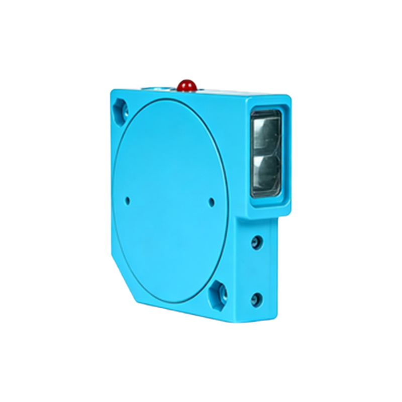
Photoelectric sensors are critical components in wire bonding machines, used for detecting wire presence, loop height, and bonding tool position. The adjustment process begins with understanding the sensor type—through-beam, retro-reflective, or diffuse. For wire bonding, diffuse sensors are common due to their ability to detect small reflective surfaces like gold or copper wires. Always refer to the machine’s manual for sensor specifications and wiring diagrams before starting adjustments.
Pre-Adjustment Checks and Safety Precautions
Before adjusting, ensure the machine is powered down and locked out to prevent accidental activation. Clean the sensor lens with a lint-free cloth and isopropyl alcohol to remove dust or bonding residue. Verify the sensor mounting is rigid and aligned with the target area. Check the power supply voltage against the sensor’s rating—typically 10-30VDC for industrial sensors. Use a multimeter to confirm stable voltage at the sensor terminals.
Setting the Sensitivity Threshold
Access the sensor’s adjustment interface, often a potentiometer or push-button on the sensor body. For wire bonding, start with the sensitivity set to the midpoint. Place a sample wire (e.g., 25µm diameter) at the sensing distance. Observe the output indicator LED—solid green usually indicates a stable signal, red or flashing means misalignment. Adjust the potentiometer clockwise to increase sensitivity until the LED is steady, then back off slightly to avoid false triggers from stray reflections.
Optimizing Sensing Distance and Angle
Position the sensor perpendicular to the wire path, typically 2-5mm from the wire for diffuse sensors. Use a feeler gauge or machine’s internal calibration tool to set the gap. If the sensor detects the bonding capillary instead of the wire, adjust the angle by 5-10 degrees off perpendicular. Test with a wire movement cycle—observe the sensor’s response time on an oscilloscope; it should be under 1ms for high-speed bonding. Adjust the distance until the sensor consistently triggers on the wire but not on the substrate.
Fine-Tuning with Dynamic Testing
After static adjustment, run a series of bonding cycles at production speed. Monitor the sensor’s output using the machine’s diagnostic software or a PLC input status. Look for missed detections (no output when wire is present) or false alarms (output without wire). For missed detections, increase sensitivity by 5-10% and recheck. For false alarms, reduce sensitivity or add a background suppression shield. Record the final settings in the machine’s parameter log for future reference.
Common Issues and Troubleshooting Tips
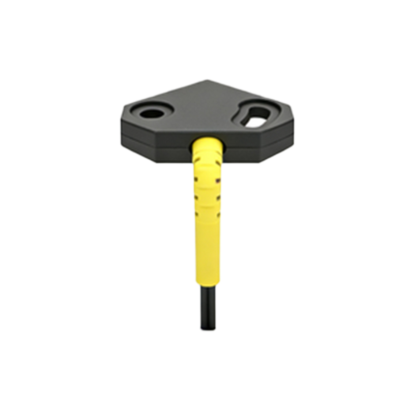
If the sensor fails to adjust, inspect for electrical noise from nearby bonder motors—add a ferrite core to the sensor cable. For reflective surfaces like gold wires, use a polarizing filter on the sensor. If ambient light interferes, install a hood over the sensor. For aging sensors, consider replacing with a newer model featuring digital adjustment for repeatable settings. Always test for at least 1000 cycles after adjustment to ensure reliability.