Introduction to Photoelectric Sensor Core
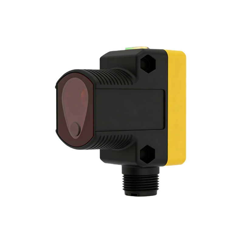
The core of a photoelectric sensor, often referred to as the inner core component, is the fundamental unit responsible for converting light signals into electrical signals. In industrial automation, this component determines the sensor's accuracy, response time, and reliability. Typically, the core includes a light emitter, a receiver, and signal processing circuitry. For electrical engineers, understanding the physical and operational characteristics of this core is essential for system integration and troubleshooting.
Light Emitter and Receiver Design
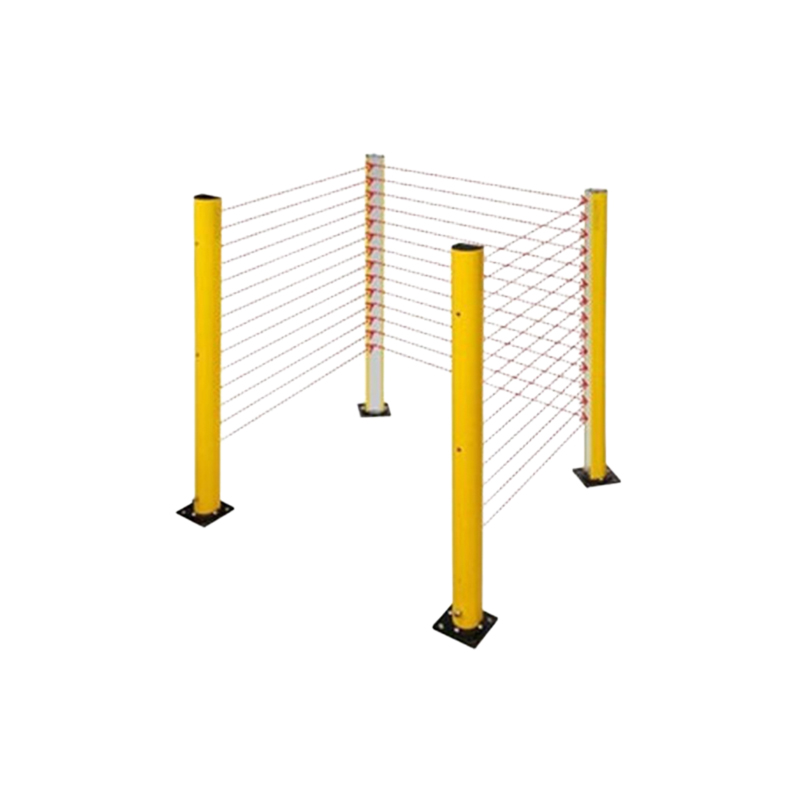
The light emitter in the core is usually a Light Emitting Diode (LED) or a laser diode, optimized for specific wavelengths such as infrared or visible red. The receiver is a photodiode or phototransistor that detects the emitted light. Key design parameters include wavelength matching, beam divergence, and optical power output. For through-beam sensors, the emitter and receiver are separated, while for retro-reflective sensors, the core integrates a lens and polarizing filter to reduce false readings from reflective surfaces.
Signal Processing Circuitry
Inside the sensor core, analog signals from the photodetector are amplified, filtered, and digitized. Advanced cores use operational amplifiers with automatic gain control to maintain performance under varying ambient light conditions. The threshold detection circuit compares the signal level against a preset reference, triggering an output switch (e.g., NPN or PNP transistor). Response time, often in microseconds, is critical for high-speed applications like conveyor belt counting or part positioning.
Environmental Protection and Packaging
The core is enclosed in robust housing, typically made of ABS plastic or metal, with IP67 or higher ingress protection. For harsh industrial environments, the core may include epoxy potting to resist vibration, moisture, and chemical exposure. Optical windows are coated with anti-reflective materials to minimize dust accumulation and maintain signal integrity. Engineers must consider temperature ranges, usually from -25°C to +55°C, for reliable operation.
Common Failure Modes and Diagnostics
Typical failures include LED degradation, photodiode saturation, or circuit drift due to temperature. Modern cores integrate self-diagnostic features, such as stability alarms that indicate marginal alignment. For troubleshooting, engineers use oscilloscopes to examine signal waveforms at the receiver output. Replacing the core module is often more cost-effective than repairing the entire sensor, especially for modular sensor families.
Selection Guidelines for Industrial Applications
When selecting a photoelectric sensor core, consider sensing distance, target material, and ambient light conditions. For transparent objects, a polarized retro-reflective core is recommended. For long-range detection (up to 100 meters), fiber optic coupled cores are preferred. Always match the core's output type (e.g., PNP, NPN, or push-pull) to the PLC input card. Additionally, consult the sensor datasheet for timing diagrams and wiring schematics.
Conclusion and Future Trends
The inner core of photoelectric sensors continues to evolve with the integration of microcontrollers and IoT connectivity. Smart cores now provide real-time data on signal strength and predictive maintenance alerts. As Industry 4.0 demands higher precision, advanced cores with multi-wavelength emitters and digital filtering are becoming standard. For electrical engineers, staying updated on core technology ensures optimal system performance and reduced downtime.