Introduction to Optical Sensors in Plotter Systems
Optical sensors play a critical role in modern plotter systems, particularly in high-precision engineering and architectural drafting. These devices, often based on photoelectric principles, detect position, speed, and alignment of the plotting head or paper feed. In the electrical engineering industry, selecting the right optical sensor directly impacts the accuracy of CAD-to-physical output, reducing errors in complex circuit layouts and mechanical drawings.
Working Principles of Photoelectric Sensors in Plotters
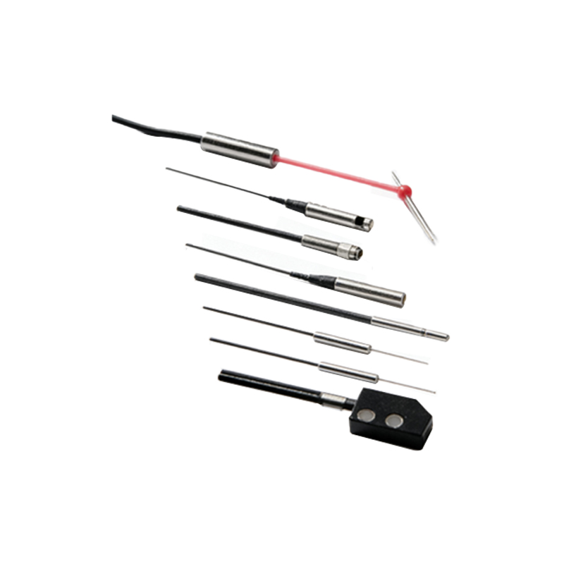
A plotter optical sensor typically uses an infrared or visible light emitter paired with a photodetector. When the light beam is interrupted or reflected by a moving component like the encoder strip or paper edge, the sensor generates a digital signal. This signal is interpreted by the plotter’s controller to adjust motor movements in real time. For example, a transmissive sensor monitors paper advance by detecting slots in an encoder wheel, while a reflective sensor ensures the pen carriage stays aligned on the x-axis.
Key Performance Parameters for Industrial Applications
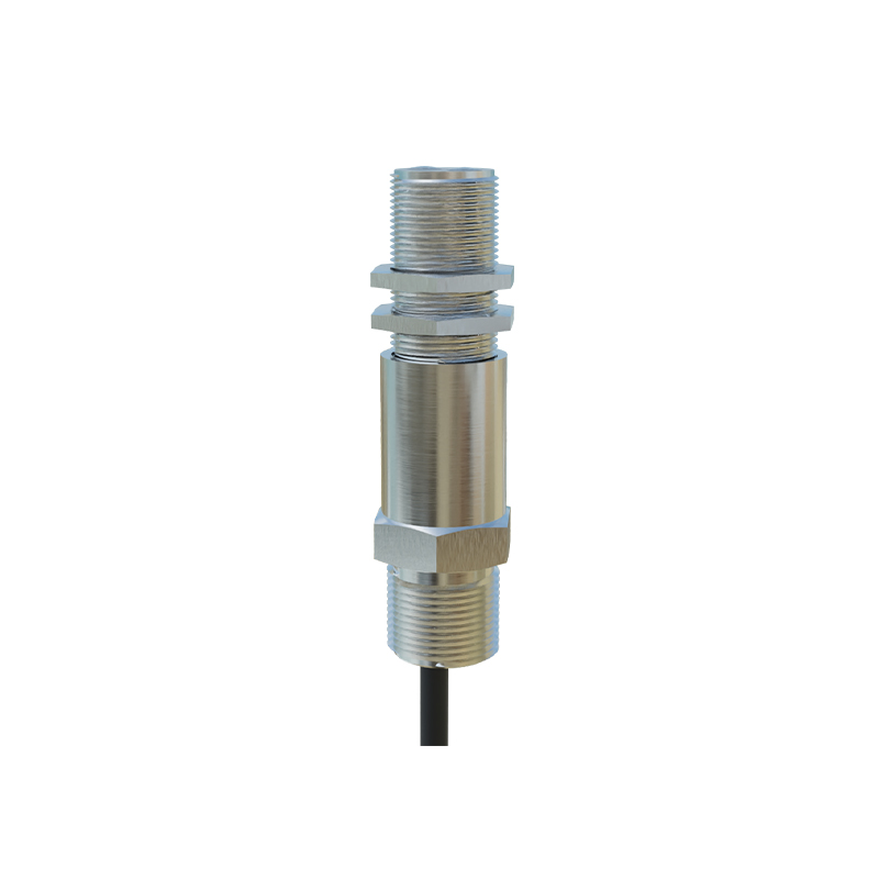
Engineers must evaluate several specifications when integrating optical sensors into plotters:
- Resolution: Measured in lines per inch (LPI) or counts per revolution, high-resolution sensors (e.g., 1200 LPI) are essential for fine-line PCB artwork.
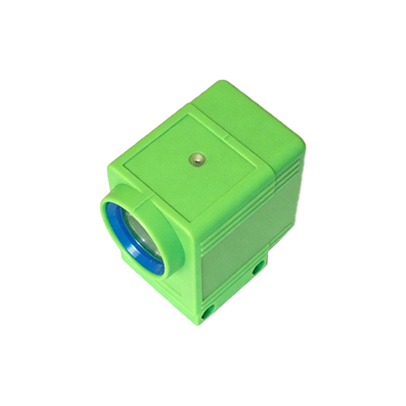
- Response Time: Fast switching speeds (under 1 microsecond) prevent jitter during rapid head movements.
- Environmental Tolerance: Dust-resistant housings and wide operating temperature ranges (-20°C to 70°C) ensure consistent performance in workshops.
- Output Interface: TTL or open-collector outputs simplify connection to microcontroller-based control boards.
Common Failure Modes and Troubleshooting
Field experience shows that optical sensor failures often stem from dust accumulation on the lens, misalignment during maintenance, or LED degradation over time. For instance, a plotter that repeatedly loses registration may have a faulty reflective sensor on the paper feed assembly. Recommended troubleshooting steps include cleaning optics with isopropyl alcohol, verifying emitter current with a multimeter, and checking solder joints on the sensor PCB.
Selection Guide for Replacement Sensors
When sourcing replacement sensors for legacy plotters (e.g., HP DesignJet or Graphtec models), consider cross-referencing part numbers like HEDS-9700 or EE-SX1108. For custom builds, choose sensors with matching slot width (e.g., 3mm for encoder wheels) and output logic level. Always verify the datasheet for electrical characteristics such as reverse polarity protection and hysteresis.
Future Trends in Plotter Optical Sensing
Emerging technologies include dual-wavelength sensors for improved contrast on glossy media and integrated ASICs that combine signal conditioning with digital filtering. In the era of IoT-enabled engineering, these sensors will likely support I²C or SPI interfaces for real-time diagnostics, enabling predictive maintenance in automated drafting environments.
结束