Introduction to Optoelectronic Sensor Feeders
Optoelectronic sensor feeders are critical components in modern automated production lines, particularly in material handling and assembly systems. These devices use light-based sensors to detect the presence, position, or orientation of workpieces, ensuring precise feeding and sorting. In this article, we explore the typical schematic diagram of an optoelectronic sensor feeder, focusing on its electrical and optical subsystems, as well as its integration into a larger automated system.
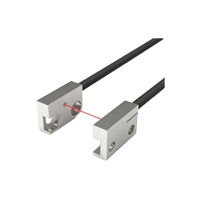
Core Components of the Schematic
A typical optoelectronic sensor feeder schematic includes several key elements: the sensor head (comprising an emitter and receiver), a control unit (often a PLC or dedicated controller), power supply modules, and actuator interfaces (such as solenoids or motors). The emitter projects a beam of light—usually infrared or visible—while the receiver detects changes in light intensity caused by the presence of an object. The schematic must clearly show power lines (e.g., 24 V DC), signal wires, and grounding paths to ensure reliable operation.
Optical Path and Detection Principle
The optical path is the heart of the system. In a typical through-beam configuration, the emitter and receiver are placed opposite each other. When a workpiece interrupts the beam, the receiver signal drops, triggering a digital output. Alternatively, in a retro-reflective setup, a reflector is used, and the sensor detects changes in reflected light. The schematic should illustrate these paths with arrows or dashed lines, and include labels for alignment tolerances and lens specifications.
Electrical Wiring and Signal Flow
The electrical wiring diagram is essential for installation and troubleshooting. It typically shows the sensor’s power input (e.g., brown wire for +V, blue for ground) and output (e.g., black wire for NPN or PNP signal). For a feeder system, the output connects to a PLC input module or a relay. The schematic must also include protection components like fuses, surge suppressors, and noise filters. Signal flow should be indicated with directional arrows, highlighting how the sensor state (HIGH/LOW) controls the feeder’s actuator.
Integration with Feeder Mechanism
The feeder mechanism, often a vibrating bowl or conveyor belt, is controlled by the sensor’s output. When the sensor detects a missing part or misalignment, it sends a signal to the controller, which then activates a solenoid or motor to adjust the feed rate or reject the part. The schematic must show this feedback loop, including timers or counters for precise sequencing. For example, a delay timer may be used to avoid false triggers from vibration.
Protection and Safety Considerations
Industrial environments demand robust protection. The schematic should include overvoltage protection diodes, reverse polarity protection, and shielded cables to minimize electromagnetic interference. Additionally, safety interlocks should be depicted, such as a emergency stop circuit that cuts power to both the sensor and feeder. Proper grounding and isolation are also critical to prevent electrical noise from affecting sensor readings.
Troubleshooting and Maintenance Tips
A well-drawn schematic simplifies troubleshooting. Common issues include misalignment of the optical path, dirty lenses, or faulty wiring. Engineers should check the sensor’s output voltage with a multimeter and verify continuity in signal lines. Regular cleaning of lenses and calibration checks are recommended. The schematic can also indicate test points for voltage measurements and LED indicators for status monitoring.
Conclusion and Best Practices
Understanding the schematic of an optoelectronic sensor feeder is essential for efficient system design and maintenance. By following industry standards, such as using color-coded wires and clear labeling, engineers can reduce downtime and improve reliability. Always consult the sensor manufacturer’s datasheet for specific pinouts and electrical ratings. With proper implementation, optoelectronic sensor feeders enhance production accuracy and throughput in industrial automation.