2026-06-07
Tech Hub
By 创始人
Understanding the Wiring of a 3-Wire Photoelectric Sensor in Industrial Automation
Introduction to 3-Wire Photoelectric Sensors
In industrial automation, photoelectric sensors are essential for non-contact detection of objects. The 3-wire configuration is a common type, offering reliable performance in harsh environments. This article provides a technical overview of the wiring, operation, and application of 3-wire photoelectric sensors, focusing on the electrical connections and best practices for engineers.
Wire Functions: Power, Ground, and Output
A standard 3-wire photoelectric sensor includes three distinct wires: the brown wire (V+), the blue wire (GND), and the black wire (output). The brown wire connects to a DC power supply, typically 10-30V DC, while the blue wire is connected to ground. The black wire carries the output signal, which can be either NPN (sinking) or PNP (sourcing), depending on the sensor model. It is critical to select the correct output type to match the PLC or controller input.
Wiring Diagram and Connection Principles
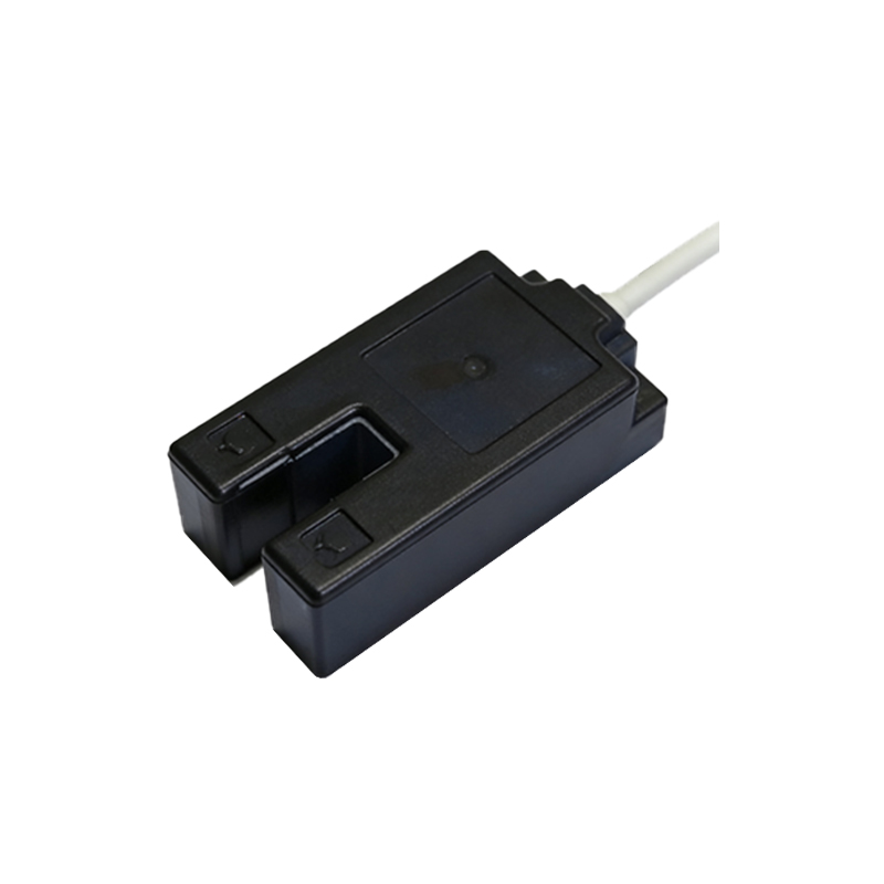
For proper installation, the brown wire should be wired to the positive terminal of the power supply, and the blue wire to the negative terminal. The black output wire connects to the input of a programmable logic controller (PLC) or a relay. In NPN sensors, the output switches to ground when activated, while in PNP sensors, it switches to the positive supply. Engineers must use a pull-up or pull-down resistor if required, and ensure the load is within the sensor's rated current capacity, typically up to 100mA.
Common Applications and Troubleshooting
3-wire photoelectric sensors are widely used in conveyor systems, packaging machines, and material handling for detecting presence, position, or counting. Common issues include incorrect wiring, voltage drop, or noise interference. For troubleshooting, first verify the power supply voltage at the brown and blue wires. If the sensor does not trigger, check the output wire with a multimeter to ensure it switches correctly. Shielding the cables and using twisted pair wires can reduce electromagnetic interference.
Safety and Compliance Considerations
When installing 3-wire photoelectric sensors, always adhere to local electrical codes and safety standards, such as IEC 61131-2. Ensure that the power supply is turned off before wiring, and use appropriate fuses or circuit breakers. For outdoor or wet environments, select sensors with IP67 or higher rating. Proper grounding of the sensor housing and cable shield prevents ground loops and protects sensitive electronics.
Conclusion: Optimizing Sensor Performance
Mastering the 3-wire photoelectric sensor wiring is fundamental for reliable automation systems. By understanding the wire functions, selecting the correct output type, and following best practices for installation and troubleshooting, engineers can maximize sensor uptime and accuracy. Always consult the sensor datasheet for specific wiring diagrams and electrical ratings to ensure seamless integration into your control system.