2026-06-07
Tech Hub
By 创始人
How Photoelectric Sensors Control Multiple Water Pumps in Industrial Systems
Introduction to Photoelectric Sensors in Pump Control
Photoelectric sensors are widely used in industrial automation for non-contact detection of objects, levels, or conditions. In water pumping systems, these sensors enable precise and reliable control of multiple pumps, optimizing energy consumption and system efficiency. By converting light signals into electrical outputs, they trigger pump operations based on predefined thresholds, such as water level or flow rate.
Working Principle of Photoelectric Sensors
These sensors consist of an emitter and a receiver, typically using infrared or visible light. When the light beam is interrupted or reflected by an object (e.g., water, a float, or a mechanical flag), the sensor’s output changes state. For pump control, a common configuration is through-beam or diffuse mode. In a multi-pump setup, sensors are placed at different water levels in a tank or reservoir. For instance, a sensor at the low-level mark signals the lead pump to start, while a sensor at the high-level mark commands all pumps to stop.
Multi-Pump Control Logic Using Sensors
To manage multiple pumps, a programmable logic controller (PLC) or a dedicated relay circuit interprets sensor signals. A typical logic includes: when the water level drops below Sensor 1 (low level), the PLC energizes Pump 1. If the level continues to fall, Sensor 2 (critical low) activates Pump 2. Conversely, as the tank fills, Sensor 3 (high level) stops Pump 2 first, then Sensor 4 (full) stops Pump 1. This staggered operation prevents frequent cycling and reduces wear on pumps.
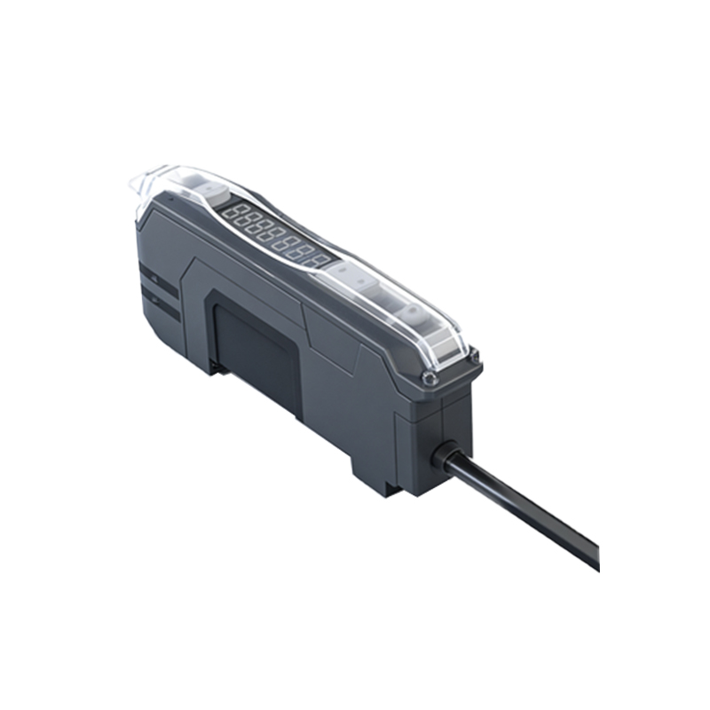
Advantages of Photoelectric Over Mechanical Switches
Photoelectric sensors offer distinct benefits over traditional float switches or pressure switches in multi-pump systems. They have no moving parts, reducing maintenance and failure risks. They also provide faster response times and can operate in harsh environments, such as wastewater or chemical plants, where mechanical switches may corrode or jam. Additionally, they allow for adjustable sensitivity and remote monitoring, enhancing system flexibility.
Practical Implementation Example
Consider a wastewater lift station with three pumps. Four photoelectric sensors are mounted vertically in the wet well: Level 1 (low), Level 2 (medium-low), Level 3 (medium-high), Level 4 (high). The PLC follows a priority rotation algorithm: Pump 1 starts at Level 2, Pump 2 at Level 3, and Pump 3 at Level 4. All pumps stop when Level 1 is reached. The sensors are wired in a fail-safe mode (normally-closed) to detect beam blockages or sensor faults, ensuring system safety.
Maintenance and Calibration Tips
Regular cleaning of sensor lenses is crucial in dusty or humid environments. Calibration should be performed annually to verify detection distances and alignment. For multi-pump systems, it is recommended to install bypass valves and manual override switches for emergency situations. Sensors should be tested with a simulated water level change to confirm correct PLC response.
Conclusion: Enhancing System Reliability
Integrating photoelectric sensors with multiple pump controls not only automates water management but also reduces energy costs by running pumps only when needed. This approach is scalable for industrial, agricultural, and municipal applications, ensuring consistent water supply or drainage without human intervention.